Distributor, Timing Setting, & Engine Check
The Distributor:The distributor does not incorporate any centrifugal or vacuum-advance controls and is fitted with a Hall transmitter.
The distributor is located as before attached to the exhaust camshaft.
Adjusting the Basic Timing Setting:
1. Start the engine and have it run until it reaches normal working temperature.
2. Check that the idling speed is 850 +/- 75 rpm. If not, adjust it to the specified value.
3. Check that the throttle switch is closed and that the switch is properly adjusted.
4. Check that the ignition timing is 14~ BTDC. (If it is out by 2~ or more, see below.) Adjust as necessary.
5. If the timing is out by more than 7~, switch off the engine.
6. Restart the engine, allow it to idle, and check the timing again.
If it is still out by more than 7~, refer to the procedure for checking the operation of the system.
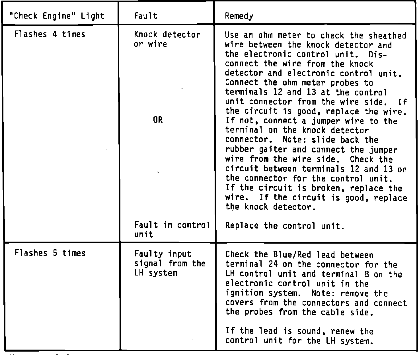
"Check Engine" Light - Fault Diagnosis Chart:
The EZK ignition has self-diagnostic capabability which displays certain faults through the "Check Engine" light located in the instrument cluster located in the dashboard. Faults will be indicated by a blinking of the light which can be interpreted by the guide below. Faults not described are most likely traceable to a wiring fault or a system component failure such as an ignition coil, etc. and must be diagnosed as such.
See following page for diagnostic chart.
Warranty Information: The following information should be added to your "Model 900/99 Failure Code/Flat Rate Manual", effective October 1, 1985:
Page No. Additional Information
2-59 & 3-11 EZK Knock Sensor Failure Code = 29164*
3-11 R & R Knock Sensor Labor Op. No. = 29164, 0.2 hour
3-11 EZK Control Unit Failure Code = 34030*
3-11 R & R EZK Control Unit Labor Op. No. = 34030, 0.2 hour
3-11 Ignition Power Stage Unit Failure Code = 34031*
3-11 R & R Ign. Power Stage Unit Labor Op. No. = 34031, 0.2 hour
3-11 & 3-33 Ignition Signal Amplifier Failure Code = 36525
3-11 R & R any relay Labor Op. No. = 36599, 0.3 hour
*Return part
s�O :
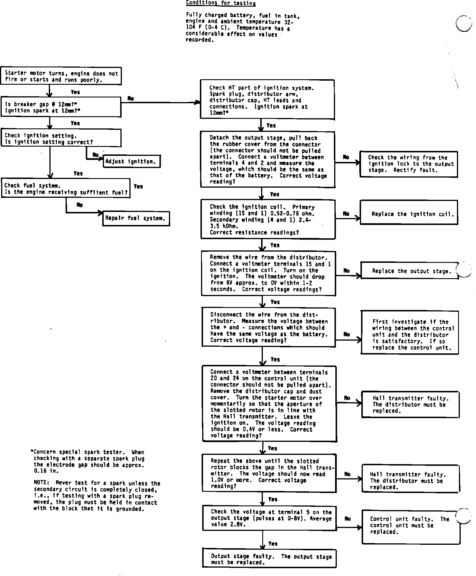
Component Diagnosis
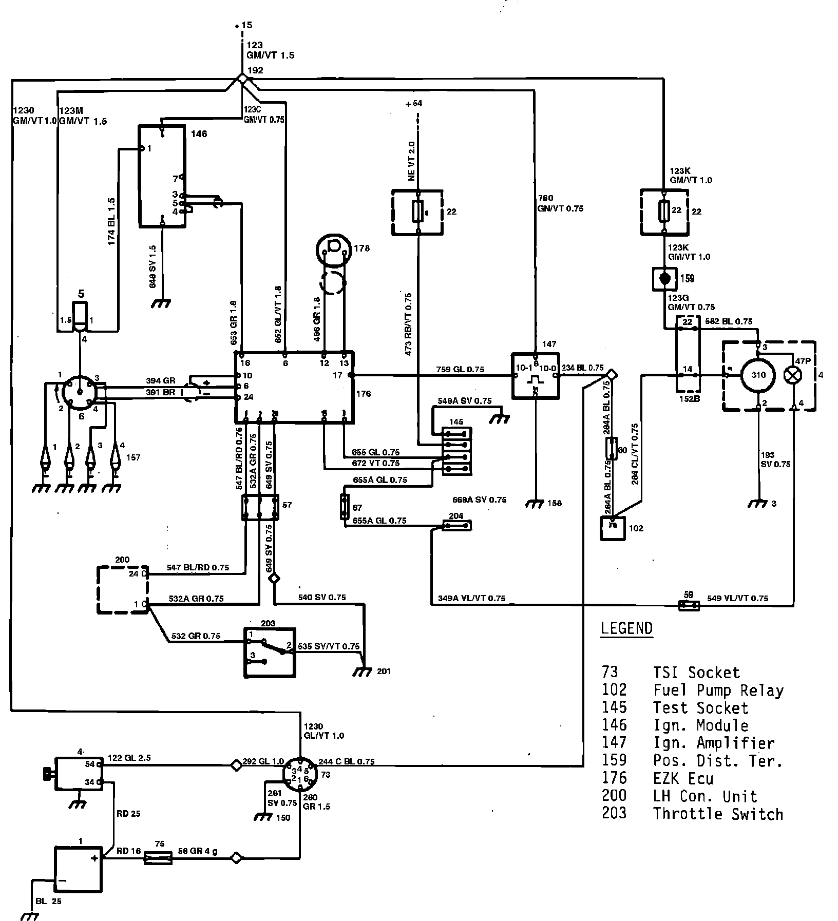
Wiring Diagram: