Diagnostic Procedures Utilizing Breakout Box and Cable
Disconnect the ECU and connect the Breakout Box and Cable.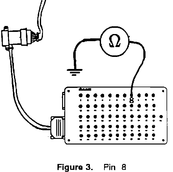
1. Check that pin 8 is grounded by measuring the resistance between pin 8 (figure 3) on the Breakout Box and a good grounding point.
If the resistance is greater than 1 ohm, check wire 615 BK between 8 of the connector and ground point G8. See wiring diagram (900) or (9000).
NOTE:
SET THE PARKING BRAKE BEFORE MOVING THE GEAR SELECTOR FROM THE PARK POSITION.
Turn the ignition switch to DRIVE and turn the Cruise Control Switch to ON. On an automatic transmission car, set the gear selector to DRIVE.
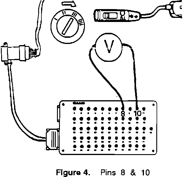
2. Check that there is battery voltage at pin 10 by measuring between pins 10 and 8 (figure 4) on Breakout Box.
900:
If there is no battery voltage, check wire 600A/600RD between pin 10 of the connector and fuse 8 on the distribution board in the engine compartment.
9000:
If there is no battery voltage, check wire 600 RD between pin 10 of the connector and fuse 2 on the distribution board in the engine compartment.
Pedal Switches:
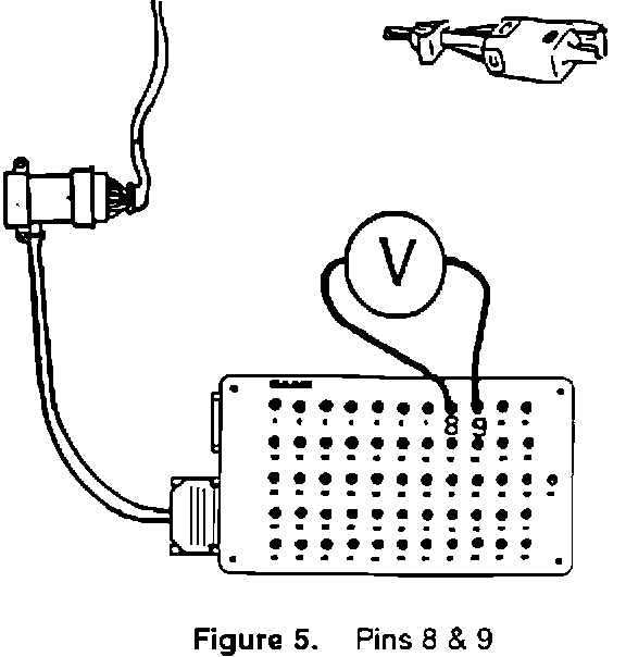
3. Check that there is battery voltage at pin 9 by measuring between pins 9 and 8 (figure 5) on Breakout Box.
If there is no voltage, check pedal switches 133 and 134 (Man) or switch 134 (AUTO).
If there is still no voltage, check for voltage at pin 1 of switch 141, red wire.
900:
If there is still no voltage, check for voltage at pin 4 of switch 141, brown wire, See wiring diagram (900) or (9000).
9000:
If there is still no voltage, check for voltage at pin 4 of switch 141, blue wire marked 600B.
Vacuum Pump:
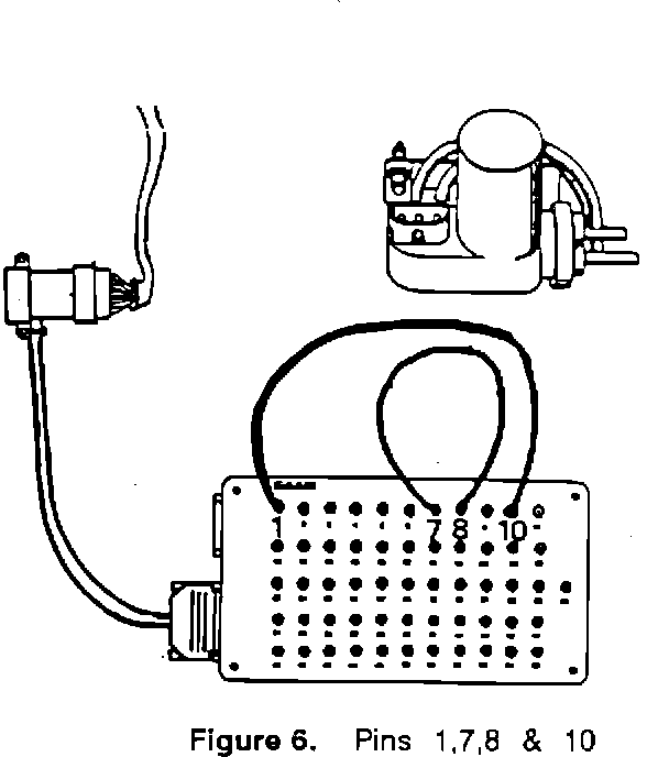
4. Check that the vacuum pump motor 187 is working by applying voltage to pin 1 (jumper wire between pins 1 and 10), grounding pin 7 (jumper wire between pins 7 and 8) and listening for the sound of the motor starting (figure 6).
Vacuum Valve:
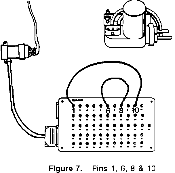
5. Check whether the vacuum valve in vacuum pump 187 closes by applying voltage to pin 1 (jumper wire between pins 1 and 10), grounding pin 6 (jumper wire between pins 6 and 8) (figure 7) and listening for the click of the valve closing.
If the vacuum pump motor or valve is not working, check the connector body and wiring harness between the vacuum pump and the connector of the ECU for open circuits.
If no fault is found in the harness, try another vacuum pump.
Vacuum Hoses:
6. If the vacuum hoses have been checked as described in Step 2, this check should not be carried out.
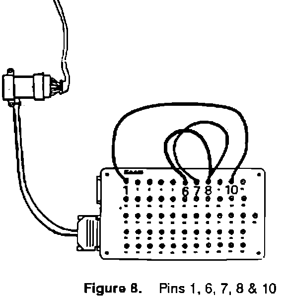
Check the vacuum hoses for cracks and leakage. A vacuum is created in the system by applying voltage to pin 1 (jumper wire between pins 1 and 10 on Breakout Box) and grounding pin 6 (jumper wire between pins 6 and 8 on Breakout Box) (figure 8) to close the vacuum valve.
Run the pump motor for about 5 seconds by grounding pin 7 (jumper wire between pins 7 and 8 on Breakout Box).
Check that there are no cracks in the vacuum servo.
HINT:
If the butterfly flap moves without "dropping back", the system is free of leaks.