A/T - Revised
9231saab01
CATEGORY
Transmission
SECTION
4
PAGE
7
ISSUE
03/92-0202
CODE
442
Subject:
Running Change: Automatic Transmission Variant
Application:
9000 Turbo Models with ASR, 1992-
With the introduction of the Traction Control System (ASR) on 1992 9000 Turbo models, a revised automatic transmission was introduced. The change to the transmission involved fitment of an improved kick-down cable. Because the end of the cable that attaches to the KDW motor is lower then the other end of the cable where it attaches to the transmission, an o-ring seal to prevent ATF leakage is installed.
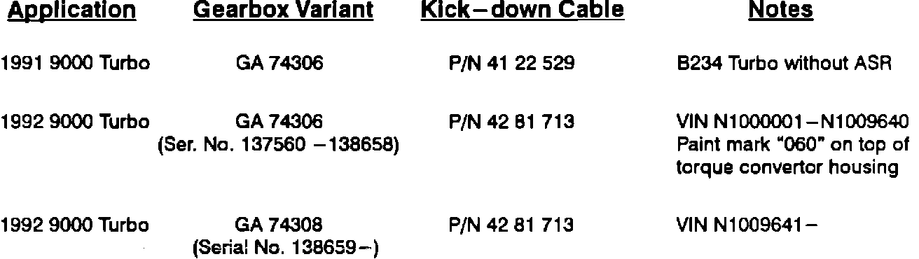
Although the new kick-down cable, P/N 42 81 713, was introduced from the start of the model year, the gearbox identification number was not changed (as compared to the M91 Turbo gearbox). As a running change, the gearbox designation was revised to make it easier to distinguish between transmissions for 9000 Turbos with ASR and those without.
Should a 1992 9000 Turbo with ASR need the transmission replaced, and the original equipment gearbox is variant GA 74306, it should be replaced with one identified as GA 74308 (exchange P/N 88 25 424). Exchange gearbox GA 74306, P/N 88 25 382, must not be used in 1992 models and vice versa, M92 exchange gearboxes must not be used in 1991 models because of the different cables used.
Kick-down Cable Installation Notes
The kick-down cable for use with ASR, P/N 42 81 713, can be distinguished from the non - ASR cable by the rubber boot that is located where the grey colored sheath is attached to the metal adjustment sleeve on the end which attaches to the KDW motor.
When replacing an ASR cable:
1. The wire on the KDW-motor end should be pre-lubed with ATF to prevent damage to the o-ring seal.
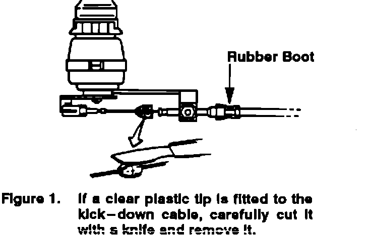
2. Remove the clear plastic tip from the cable prior to installation if the cable is fitted with it (Figure 1).
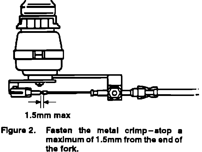
3. The metal crimp - stop that is loose on a replacement cable should be crimped so that there is a maximum clearance of 1.5 mm between the end of the fork and the crimp stop (Figure 2). Fasten the crimp - stop using pliers with a rounded die, such as electrical terminal crimping pliers.