Fuel Pressure Regulator: Service and Repair
WARNING: Do not allow smoking or the use of open flames in the area where work on the fuel system is taking place. Anytime the fuel system is being worked on, disconnect the negative battery cable, except for those tests where battery voltage is required.NOTE: Support fuel rail to avoid damaging during bench repairs.
NOTE: The fuel pressure regulator can be replaced without removing the fuel rail.
FUEL PRESSURE REGULATOR ASSEMBLY REMOVAL
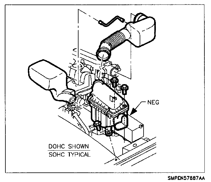
1. Remove air intake, air filter cover and PCV hose.
WARNING: Whenever fuel line fittings are loosened or disconnected, wrap a shop cloth around fitting while connecting gauge, to collect fuel. Place the cloth in an approved container.
Fuel System Pressure Relief:
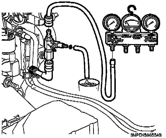
2. Connect fuel gauge bar kit (Saturn Tool) SA9127E to fuel pressure test port. Use 900 adaptor SA9403E.
3. Install bleed hose into an approved container and open valve to bleed system pressure. Once pressure is bled, remove gauge from pressure test port and recap it.
WARNING: Whenever fuel line fittings are loosened or disconnected, wrap a shop cloth around fitting while connecting gauge, to collect fuel. place the cloth in an approved container.
4. Remove throttle control cable bracket bolts, disconnect cable from throttle lever and lay over intake manifold.
5. Remove the vacuum hose to the fuel pressure regulator.
WARNING: Place a shop cloth under the fuel rail in the area near the fuel pressure regulator to catch any residual fuel that may leak from the pressure regulator.
Fuel Pressure Regulator Retaining Clip:
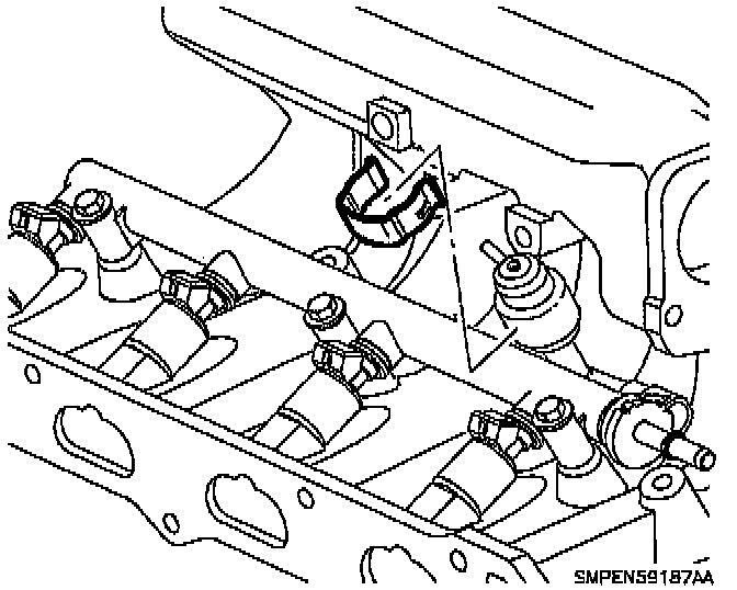
6. Remove and discard the snap ring holding the fuel pressure regulator to the fuel rail socket.
7. Remove the fuel pressure regulator from the fuel rail socket by pulling upward.
NOTE: To prevent damage to plastic socket, do not use any tools when removing the fuel pressure regulator.
8. Remove and discard from the fuel pressure regulator or from the fuel socket:
- Plastic back-up ring
- Upper 0-ring (large 0-ring)
- Filter screen
- Lower 0-ring (small 0-ring)
NOTE: When removing the filter screen, be careful not to drop the lower 0-ring into the fuel rail. If dropped into the rail the 0-ring must be retrieved. If not retrieved, a new fuel rail must be used.
9. Inspect fuel rail socket for foreign material and clean if necessary.
NOTE: When cleaning or servicing the fuel rail pressure regulator socket, care must he taken to assure that the fuel rail surfaces that mate to the regulator 0-rings are not scratched.
INSTALLATION
Fuel Pressure Regulator Components:
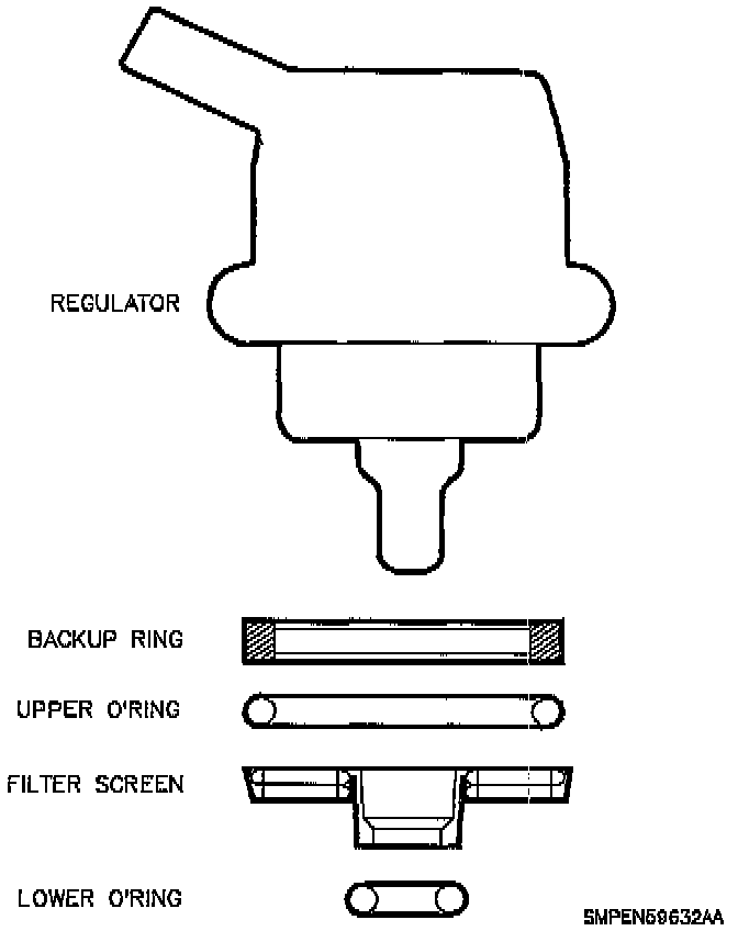
1. When the fuel pressure regulator is disassembled the following components must be replaced with new parts:
- Back-up ring
- Upper 0-ring (large 0-ring)
- Filter screen
- Lower 0-ring (small 0-ring)
2. Lubricate the upper and lower 0-rings with clean engine oil prior to assembling the fuel pressure regulator.
NOTE: Assemble the back-up ring, upper 0-ring, filter screen and lower 0-ring to the regulator. Next, install the regulator assembly to the fuel rail socket. This procedure will prevent dropping the lower 0-ring into the fuel rail.
Fuel Pressure Regulator Assembly:
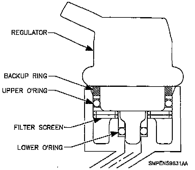
3. Assemble the fuel pressure regulator as shown.
4. Using hand pressure only, install the fuel pressure regulator assembly into the fuel rail socket. Rotating the fuel regulator one quarter turn while installing will assist in the assembly process.
5. Install the new snap ring.
Installing Fuel Pressure Regulator Retainer:
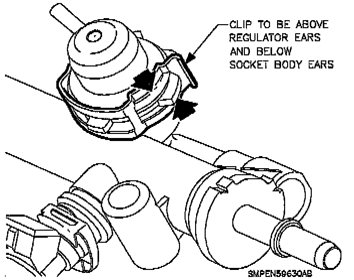
NOTE: Ensure that the snap ring is installed correctly the lower side of the clip surrounds the socket (downside) and the small side of the clip (top side) surrounds the fuel pressure regulator. Ensure the snap ring is fully engaged over the socket tabs and the fuel pressure regulator body. (Reference illustration.)
Positioning Regulator On Fuel Rail:
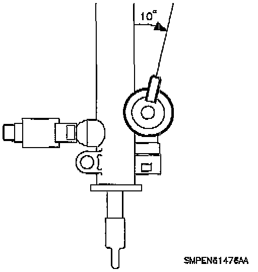
NOTE: Position the fuel pressure regulator tube at a 10 degree angle to the fuel rail body.
6. With engine off and ignition on, pressurize system and check for fuel leaks.
7. Connect PCV valve hose and connect vacuum line to fuel pressure regulator. Make sure they are fully seated.
8. Install throttle cable bracket bolts and attach cable if disconnected.
Torque to 25 N.m (19 ft-lbs)
9. Prime fuel system.
a. Cycle ignition on for 5 seconds and then off for 10 seconds.
b. Repeat step 9a twice.
c. Crank engine until it starts (maximum starter motor cranking time is 20 seconds.)
d. If engine does not start, repeat steps 9a-9c.
10. Install air intake tube and air filter cover.