Overhaul
WARNING: The modulator drive gears are under spring load and will turn during disassembly. After removing modulator drive gear cover, exercise extreme care not to place fingers into the gear set, since fingers can be pinched by rotating gears.CAUTION: Do not attempt to repair damaged motor packs or modulator assemblies. Other than modulator drive gear replacement, repair of these assemblies is not to be attempted. Do not lubricate or oil motor pack assembly.
DISASSEMBLY
1. Remove two-gear cover-to-modulator TORX(r) head screws and separate gear cover from modulator.
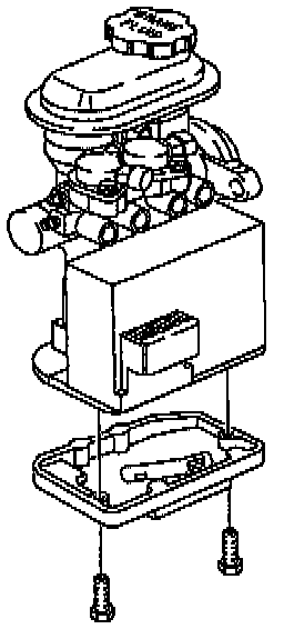
NOTE:
^ If only the motor pack is being replaced, perform step 3 of this disassembly procedure then perform steps 6 through 9 of the assembly procedures. If removing the master cylinder, perform steps 3 through 6 of this disassembly procedure then perform steps 1 through 5 and 8 and 9 of the assembly procedures.
^ If the modulator is the only unit being replaced, mark the modulator drive gears before removal so that they can be installed onto new modulator in the same location.
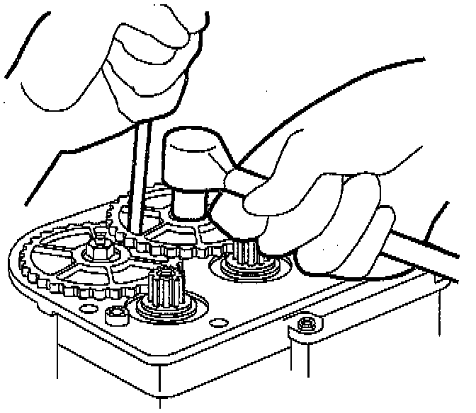
2. Remove three modulator drive gear-to-modulator drive shaft retaining nuts and remove gears from modulator.
CAUTION: Do not allow gear to turn while removing retaining nut, since the modulator piston can hit the top of the modulator bore, damaging the piston. Place a screwdriver through the holes in the gears (not between the gears) into the recessed hole in the modulator base. This will prevent the gear from turning, aiding in gear removal.
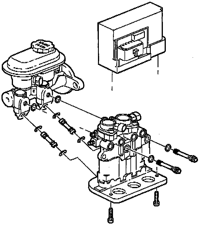
3. Remove two motor pack-to-modulator T0RX(r) head screws and separate motor pack from modulator.
4. Remove two modulator-to-master cylinder through-bolts and separate modulator from master cylinder.
5. Remove two transfer tubes with 0-rings from master cylinder or modulator.
6. Remove through-bolt 0-rings from master cylinder and modulator.
ASSEMBLY
1. Lubricate new transfer tube 0-rings with clean brake fluid.
CAUTION: New 0-rings and transfer tubes must be used when performing this step.
2. Install transfer tubes (with 0-rings) into modulator by pressing in tubes by hand, until bottomed in modulator.
3. Lubricate new through-bolt 0-rings with clean brake fluid and install into master cylinder and modulator.
4. Install master cylinder onto modulator.
5. Install two modulator-to-master cylinder through bolts.
^ Torque to 16.5 Nm (146 inch lbs.)
6. Position modulator drive gears onto drive shafts and install three gears to drive shaft retaining nuts.
^ Torque to 8.5 Nm (75 inch lbs.)
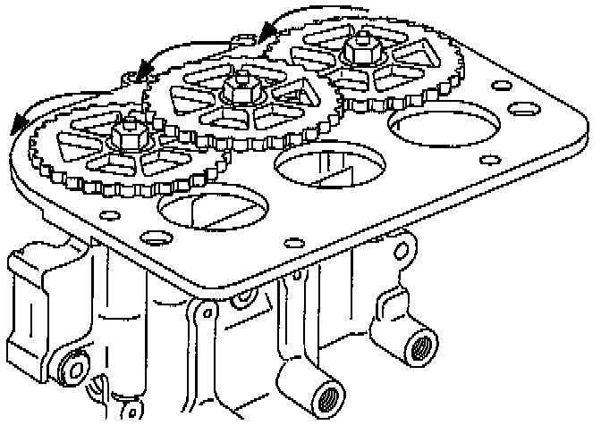
7. With the modulator upside down and the gears facing you, rotate each gear counter-clockwise until movement stops. This procedure will position the pistons very close to the top of modulator bore, simplifying the brake bleeding procedure.
8. Position motor pack onto modulator aligning the three motor pack gears with the modulator gears and install two motor pack to modulator T0RX(r) head screws.
^ Torque to 4.5 Nm (40 inch lbs.)
9. Install gear cover onto modulator assembly with two T0RX(r) head screws.
^ Torque to 2.75 Nm (25 inch lbs.)