Recommended Refinishing Procedure
INTRODUCTIONIn manufacturing the brake rotor, tolerances of the braking surfaces for flatness, parallelism, and lateral runout are held very close. The maintenance of close tolerances on the shape of the braking surfaces is necessary to prevent brake roughness and brake noise. In addition to these tolerances, the surface finish must be held to a specified range. The control of the braking surface finish is necessary to avoid pulls and erratic performance and to extend lining life. When performing routine brake maintenance, rotors should not be refinished, unless there is a brake pulsation caused by the rotors or the rotors are excessively scored.
Scoring of the rotor surfaces not exceeding 1.5 mm (0.060 in.) in depth, which may result from normal use, is not detrimental to brake operation.
PROCEDURE
NOTE: A brake rotor is a precision machined part. It must be properly machined to provide proper service.
1. All rust and corrosion must be removed from the mounting surfaces of the rotor. Use a wire brush or a wire wheel and a drill to remove all corrosion and scale from the mounting surfaces of the rotor.
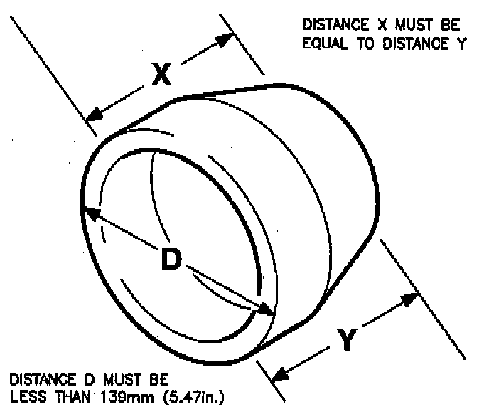
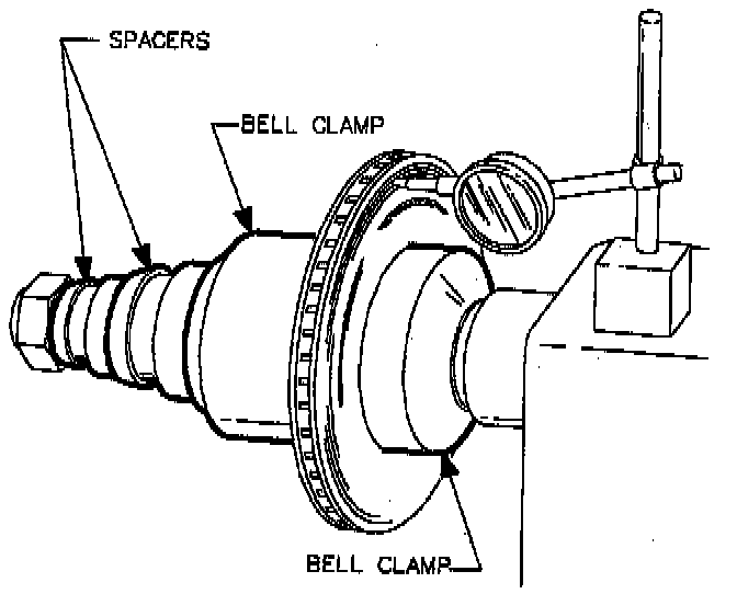
2. Make sure the correct "bell clamps" are used to mount the brake rotor on the brake lathe. Some bell clamps may appear to fit flush inside the brake rotor, but actually they may be too large, forcing the brake rotor to "wobble" when it turns on the lathe. Bell clamp outside diameter ("D") must be less than 139 mm (5.47 in.). If a brake rotor does not turn on a plane that is parallel to the brake lathe's cutting tip, lateral runout will be machined into the brake rotor.
3. Both surfaces of the inside bell clamp must be parallel or the rotor will not turn on a parallel plane with the cutting tip. If a bell clamp is dropped or damaged in any way, contact the brake lathe's manufacturer to obtain a new bell clamp.
4. Use the largest possible "spacers" to hold the bell clamps on the lathe's spindle. This makes sure that there is the most mass possible on the spindle, helping the rotor to turn on a parallel plane with the brake lathe's cutting tip.
5. Use a magnetic dial indicator to make sure that the rotor turns squarely on the brake lathe. Attach the dial indicator on the lathe and check rotor runout. Mark the highest point of lateral runout on the rotor. Loosen the attachment hardware and rotate the rotor 180° while holding the inside bell clamp in its original position. Tighten attachment hardware and recheck rotor runout. Any runout must follow the rotor. The marked high spot must remain the high spot. If not, some problem exists in the attachment of the rotor on the lathe, such as bent bell clamps, incorrect bell clamps, or untrue mounting surfaces.
6. Visually check the machined rotor's surface finish. Any deterioration in surface finish quality usually indicates worn cutting tips. Always use the cutting tips recommended by the brake lathe's manufacturer.
7. A secondary finishing operation improves rotor surface finish. Some brake lathe manufacturers offer lathe-mounted tools for this purpose. In no such tool is available, Saturn recommends using silicon carbide 150 grit emery paper mounted on a sanding block. Using moderate pressure, hold paper against the rotor as it turns in the lathe for 90 seconds per side.
8. Throughly clean machined rotors with a spray solvent such as Saturn Choke and Brake Cleaner or equivalent.