Removal and Installation
FRONT ROTORREMOVAL
CAUTION: MAKE SURE VEHICLE IS PROPERLY SUPPORTED AND SQUARELY POSITIONED ON HOIST. TO HELP AVOID PERSONAL INJURY, PROVIDE ADDITIONAL SUPPORT TO THE OPPOSITE END OF THE VEHICLE THAT COMPONENTS WILL BE REMOVED FROM.
1. Raise vehicle on hoist.
2. Remove wheel and disc assembly.
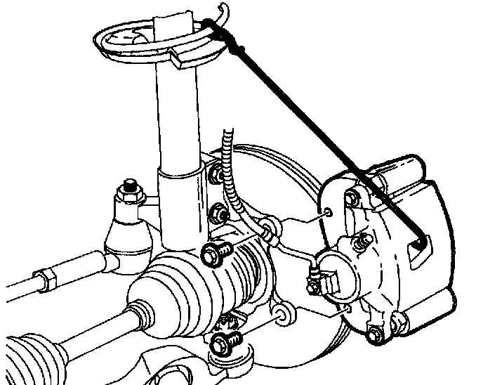
3. Remove caliper support to steering knuckle bolts; remove caliper assembly and suspend it from the strut spring with mechanics wire.
4. Remove rotor.
Front Rotor Thickness
New: 18.0 mm (0.710 inch)
Minimum after Turning: 16.1 mm (0.633 inch)
Discard: 15.8 mm (0.625 inch)
IMPORTANT: Refer to "Inspecting and Refinishing Brake Rotors".
INSTALLATION
1. Install rotor onto wheel hub.
NOTICE: Clean caliper support bracket fasteners thoroughly with brake and choke cleaner (P/N 21007432 or equivalent). Apply a high temperature thread locker (Loctite 272 or equivalent) to caliper support bracket fasteners. If Loctite 272 (or equivalent) is not available, new caliper support bracket fasteners must be used.
2. Install caliper support onto steering knuckle
Torque: Brake Caliper-to-Steering Knuckle: 110 Nm (81 ft. lbs.)
NOTICE: Before installing wheels, remove rust or corrosion from wheel mounting surfaces and brake rotors/drums. Failure to do so can cause wheel nuts to loosen in service.
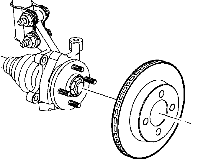
3. Position wheel onto hub.
4. Install wheel nuts and tighten in a crisscross pattern. Repeat tightening pattern to be sure torque is correct.
Torque: Wheel Nut: 140 Nm (103 ft. lbs.)
5. Lower vehicle from hoist