Evaporator Hose Assembly Replacement
EVAPORATOR HOSE ASSEMBLY REPLACEMENTTOOLS REQUIRED
- J 43600 ACR 2000 Air Conditioning Service Center
- J 39400-A Halogen Leak Detector
REMOVAL PROCEDURE
1. Disconnect the negative battery cable.
2. Recover the refrigerant. Refer to Refrigerant Recovery and Recharging.
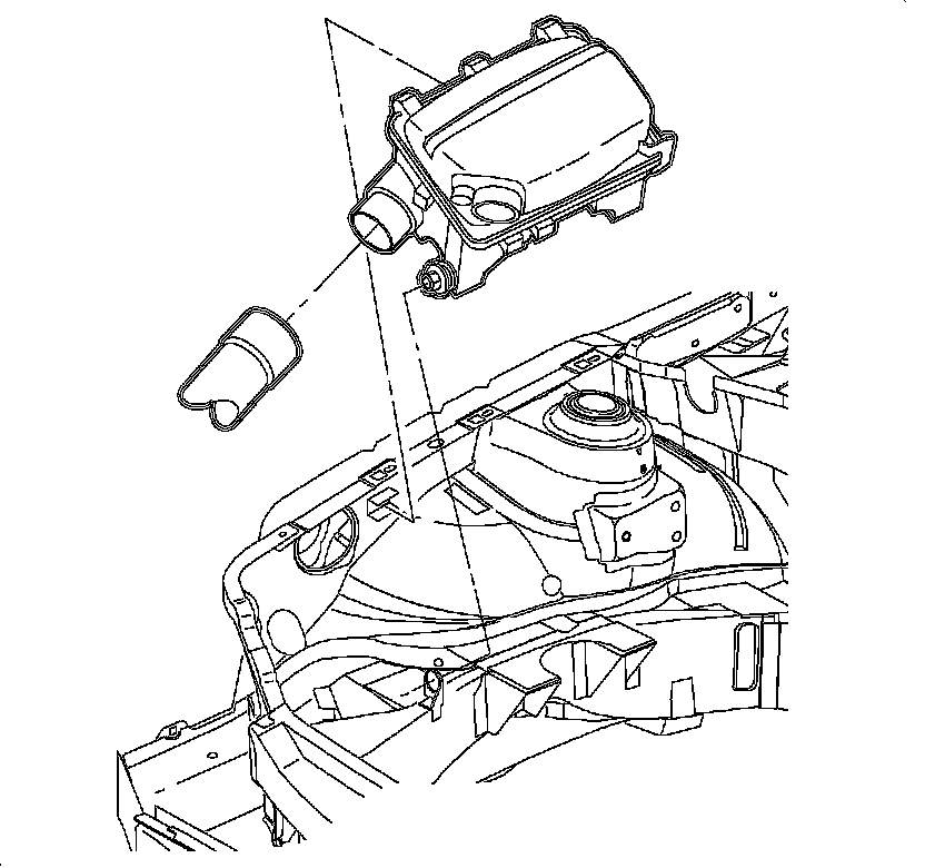
3. Remove the air cleaner assembly.
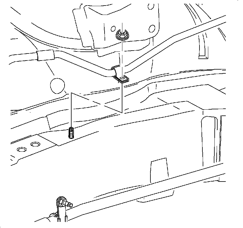
4. Remove the fastener that secures the evaporator hose assembly clamp at the engine mount area.
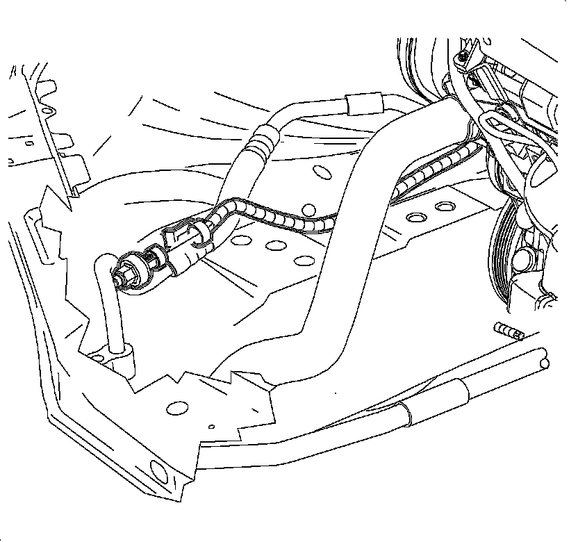
5. Disconnect the electrical connector to the refrigerant pressure sensor.
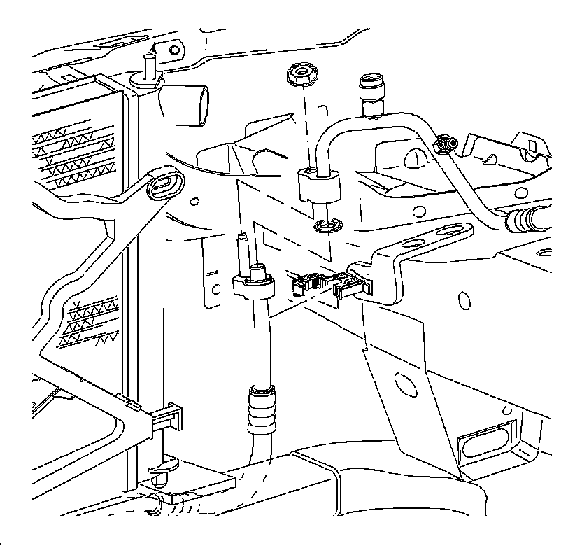
6. Remove the nut that secures the evaporator hose assembly to the condenser hose.
CAUTION: Do not remove hoses or lines before system is fully discharged. System may be under pressure and contact with R134a may cause personal injury.
7. Remove the evaporator hose assembly from the condenser hose.
8. Install the cap on the evaporator hose to prevent dirt and moisture entry.
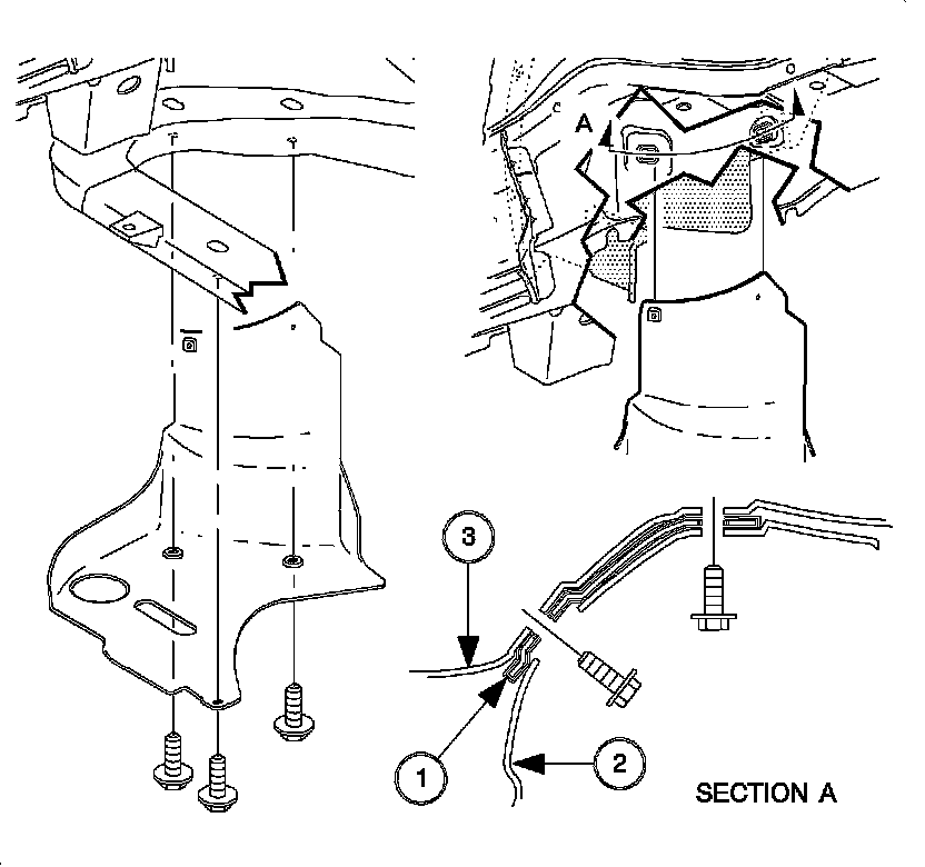
9. Raise the vehicle. Refer to Vehicle Lifting.
10. Remove the splash shield fasteners.
11. Remove the splash shield.
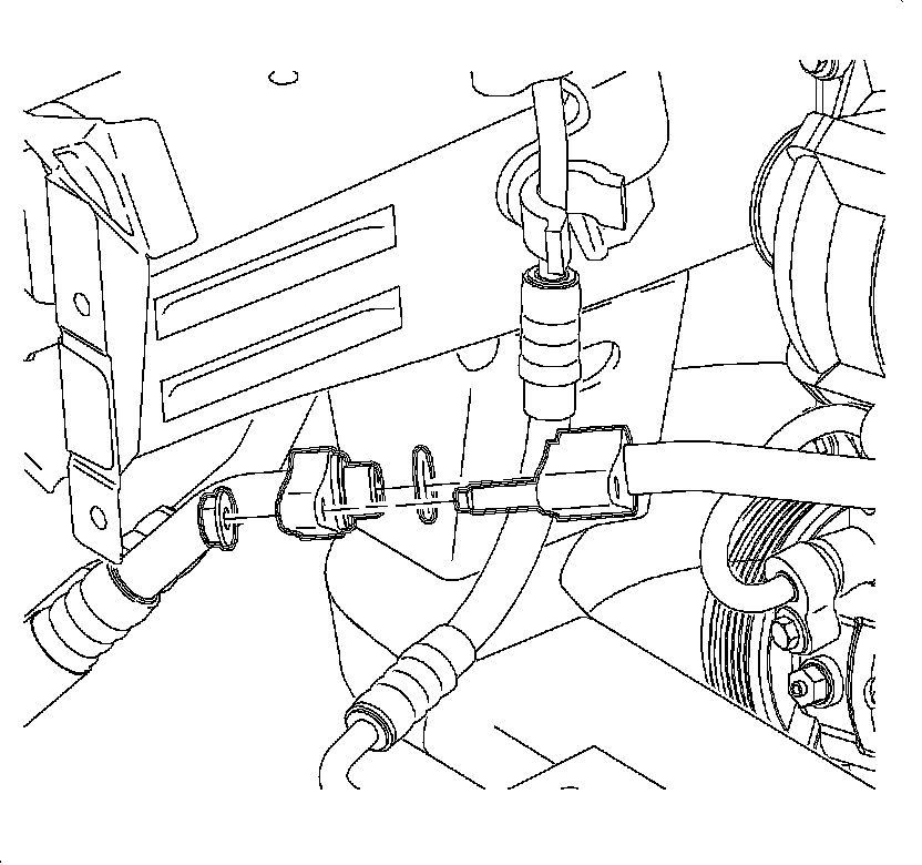
12. Remove the nut that secures the evaporator hose assembly to the suction pipe.
13. Remove the evaporator hose assembly from the suction pipe.
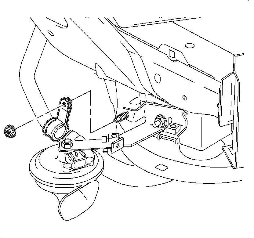
14. Remove the bracket clamp that secures the evaporator hose assembly to the horn.
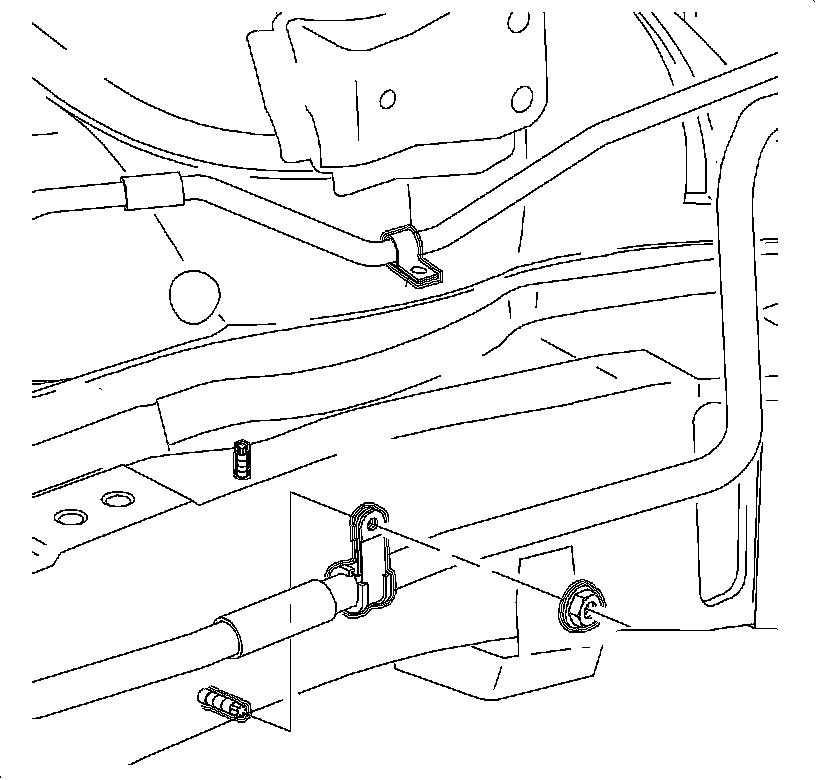
15. Remove the nut that secures the evaporator hose assembly clamp at the rail.
16. Lower the vehicle.
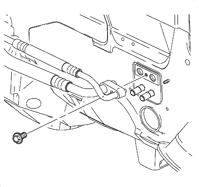
17. Remove the bolt that secures the evaporator hose assembly to the thermal expansion valve (TXV).
18. Remove the evaporator hose assembly from the TXV.
19. Install the cap on the TXV to prevent dirt and moisture entry.
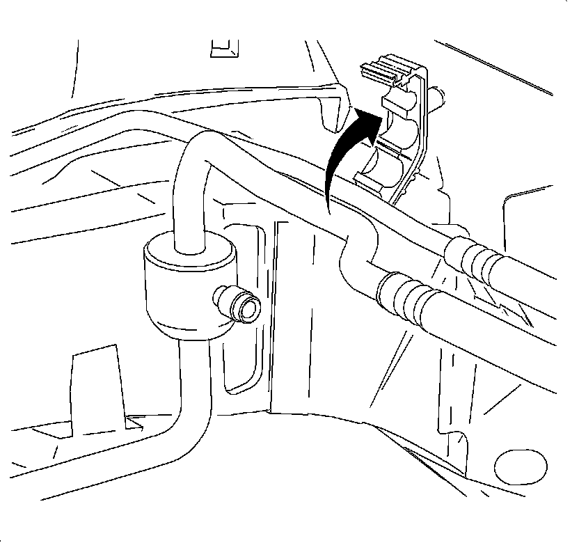
20. Remove the evaporator hose assembly from the clamp at the cowl.
21. Remove the O2 sensor clip from the evaporator hose assembly.
22. Remove the nut that secures the harness bracket to the cowl and open the harness clip.
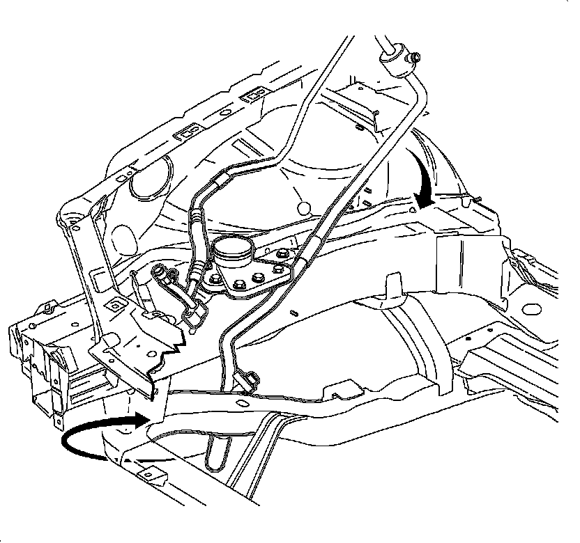
23. Remove the evaporator hose assembly from the vehicle.
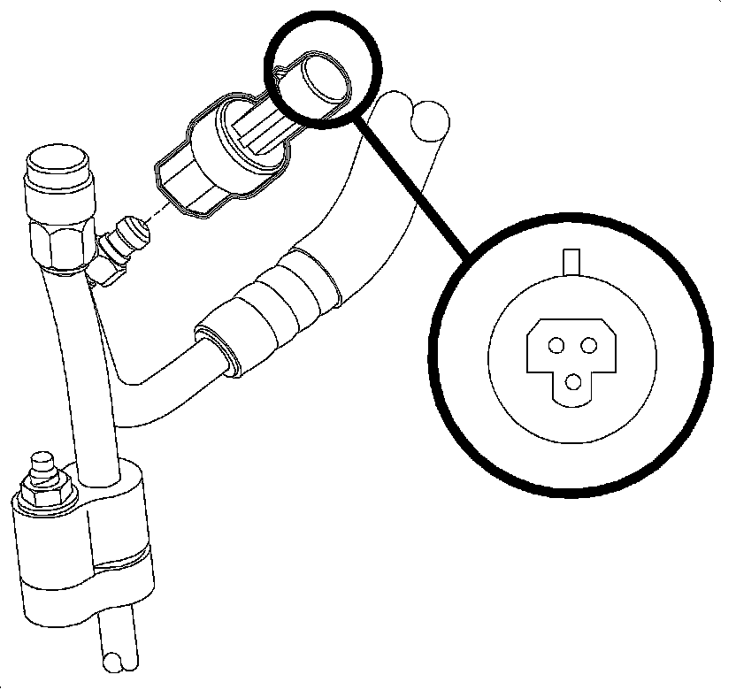
24. Remove refrigerant pressure switch from the evaporator hose assembly.
INSTALLATION PROCEDURE
NOTE: Refer to Fastener Notice in Service Precautions.
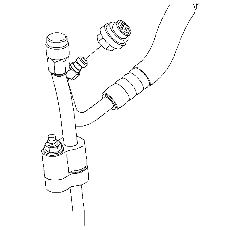
1. Install the refrigerant pressure switch to the evaporator hose assembly.
Tighten the switch to 7 N.m (62 lb in).
2. Position the evaporator hose assembly into vehicle.
- Position the evaporator hose inside of the wiring harness and outside of the fuel lines.
- Position the evaporator hose rearward of the wiring harness at the front of the dash with the oxygen sensor harness behind the evaporator hose.
3. Remove the shipping caps from the TXV and the evaporator hose assembly.
4. Install new O-rings on the evaporator hose assembly.
5. Position the evaporator hose assembly to the TXV.
6. Install the bolt that secures the evaporator hose to TXV.
Tighten the bolt to 7 N.m (62 lb in).
7. Remove the shipping cap from the evaporator hose assembly and from the condenser hose.
8. Install a new seal washer to the evaporator hose assembly.
9. Install the nut that secures the evaporator hose to the condenser hose.
Tighten the nut to 12 N.m (106 lb in).
10. Install the evaporator hose assembly into the clamp at the cowl.
11. Install the oxygen sensor harness clip onto the evaporator hose assembly.
12. Close the steel harness clip and install the nut.
Tighten the nut to 6 N.m (53 lb in).
13. Install the evaporator hose assembly clamp at the mount area.
Tighten the nut to 5 N.m (44 lb in).
14. Raise the vehicle.
15. Install a new seal washer to the evaporator hose assembly.
16. Install the nut that secures the evaporator hose to the suction pipe.
Tighten the nut to 12 N.m (106 lb in).
17. Install the nut that secures the evaporator hose assembly clamp to the horn bracket.
Tighten the nut to 10 N.m (89 lb in).
18. Install the evaporator hose assembly clamp at the rail and install the nut.
Tighten the nut to 5 N.m (44 lb in).
19. Install the lower cradle splash shield (1).
20. Install the splash shield fasteners.
Tighten the fasteners to 5 N.m (44 lb in).
21. Lower the vehicle.
22. Connect the refrigerant pressure sensor electrical connector.
23. Install the air cleaner assembly.
24. Connect the negative battery cable.
25. Evacuate and recharge the A/C system. Refer to Refrigerant Recovery and Recharging.
26. Using J 39400-A , leak test the fittings of the component.