Disassembly/Assembly
Fig. 11 Power rack & pinion steering gear seals & components. 1985-88 Exc. XT models:
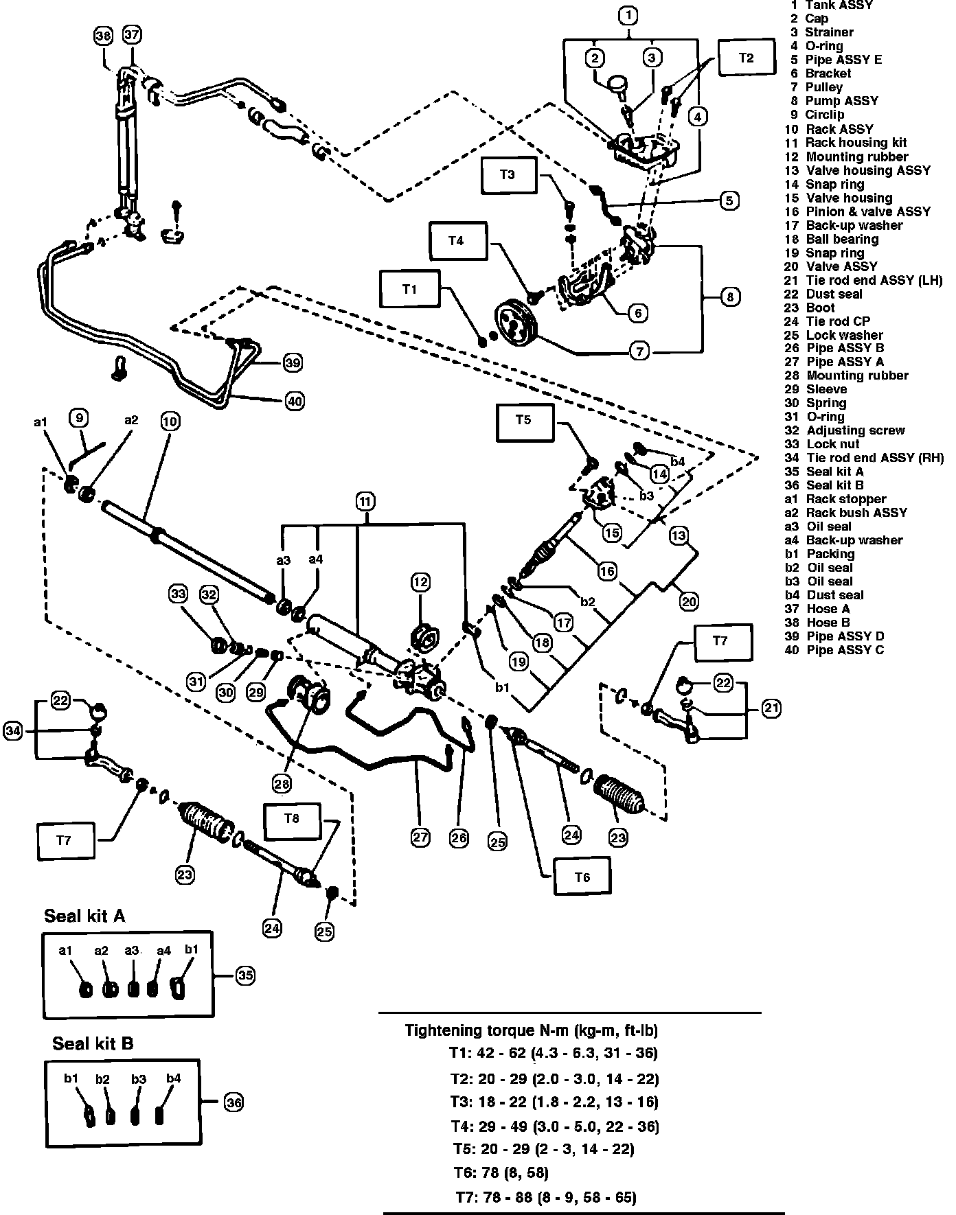
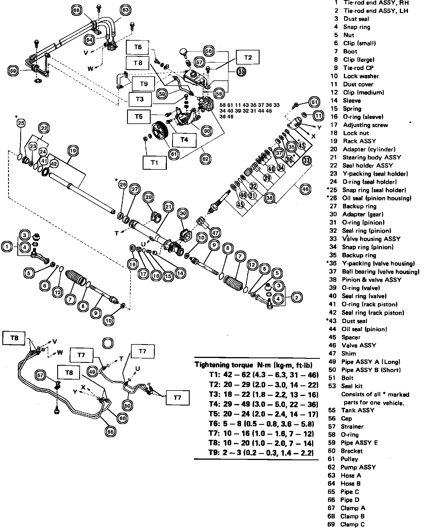
Fig. 12 Power rack & pinion steering gear seals & components. 1985-88 XT models:
Disassemble
1. Place tool No. 926200000 in suitable vise, then attach steering gear to tool.
2. Remove clip from boot, then push boot toward tie rod end, Figs. 11 and 12.
3. Remove boot, big band and medium clips, then push rack fully into gear box.
4. Straighten tie rod lock washer, using care not to strike rack.
5. Loosen ball joint, using wrench tool No. 925700000 and spanner tool No. 9262300000, and remove tie rod from rack.
6. Loosen locknut, then remove adjusting screw.
7. Remove spring and sleeve, then remove dust seal of dust cover, if equipped.
Assemble
1. Apply a suitable grease to rack teeth and sliding portion of rack, Figs. 11 and 12, using care not to apply grease to threaded end of rack.
2. Apply a suitable lubricant to sleeve insertion hole and dust seal or dust cover, if equipped.
Fig. 11 Power rack & pinion steering gear seals & components. 1985-88 Exc. XT models:
3. On all models except XT, press fit dust seal into gear box housing until distance between gearbox and dust seal is .08 inch or less, Fig. 11.
Fig. 12 Power rack & pinion steering gear seals & components. 1985-88 XT models:
4. On XT models, apply a suitable lubricant to dust cover, then position on input shaft. Push dust cover onto input shaft until it lightly contacts housing shoulder. Clearance between lip of dust cover and housing shoulder should be 0-.020 inch. Do not use excessive pressure when seating dust cover against housing cover, as this may cause binding in the steering system.
5. On all models, apply a suitable lubricant to sliding surface of sleeve and spring seat, then insert sleeve into pinion housing assembly.
6. Insert spring into sleeve screw, then pack screw with a suitable grease and install.
7. Adjust rack and pinion backlash as follows:
a. Torque adjusting screw to 3.6 ft.lbs. to seat sleeve against rack, then back off 1/2 turn.
b. Rotate adjusting screw until resistance is felt, then back off 1/24 turn (15 degrees).
c. Torque locknut to 22-36 ft.lbs.
8. Install new lock washer on threaded portion of rack end, then align cutout portion of rack and nail of washer and torque ball joint to 58 ft.lbs.
9. Temporarily remove steering gear from stand, then bend lock washer toward plain surface of ball joint.
10. Apply a suitable grease to groove of tie rod, then ensure boot is positioned without unusual inflation or deflation.
11. Install clips on boot, then assemble boot to gear box while retaining gear flange. Fold back boot flange until large clip cannot be seen.
12. Install small boot end clip, ensuring boot end is positioned in groove on tie rod.
13. Screw in tie rod end locknut and tie rod end onto tie rod, then tighten locknut .59 inch from back of nut to threaded portion.