Automatic Transaxle Replacement
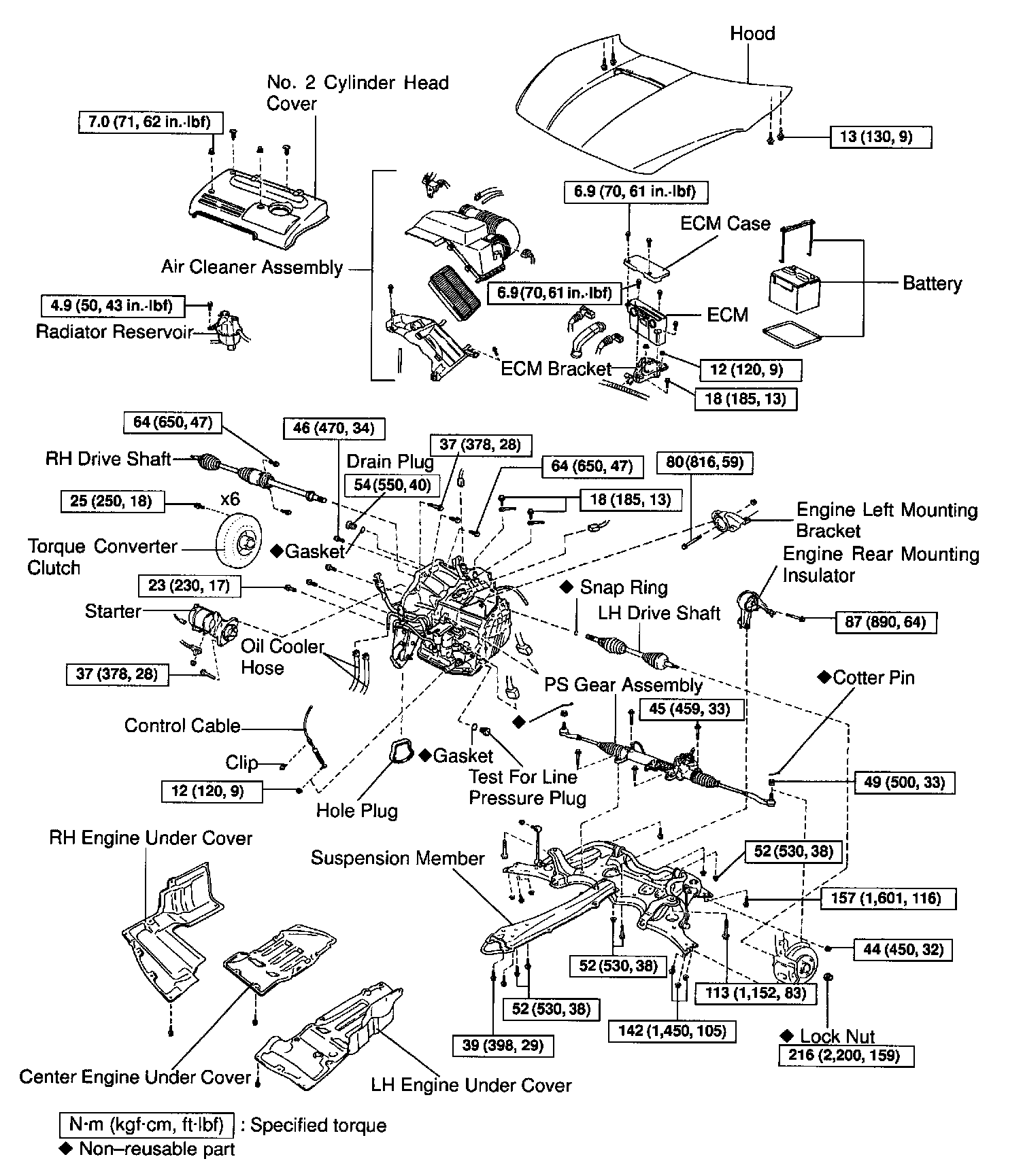
REMOVAL
1. REMOVE HOOD
Torque: 13 Nm (130 kgf-cm, 9 ft. lbs.)
2. REMOVE BATTERY
3. REMOVE ECM AND ECM CASE
Torque: 6.9 Nm (70 kgf-cm, 61 inch lbs.)
4. REMOVE ECM BRACKET Torque:
Bolt: 18 Nm (185 kgf-cm, 13 ft. lbs.)
Nut: 12 Nm (120 kgf-cm, 9 ft. lbs.)
5. REMOVE AIR CLEANER ASSEMBLY
6. REMOVE No.2 CYLINDER HEAD COVER
Torque: 7.0 Nm (71 kgf-cm, 62 inch lbs.)
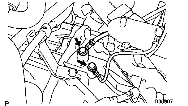
7. REMOVE 2 GROUND CABLES
Torque: 18 Nm (185 kgf-cm, 13 ft. lbs.)
8. DISCONNECT CONTROL CABLE FROM CLAMP
9. DISCONNECT INPUT TURBINE SPEED SENSOR CONNECTOR
10. DISCONNECT COUNTER GEAR SPEED SENSOR CONNECTOR
11. REMOVE VEHICLE SPEED SENSOR CONNECTOR
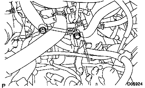
12. REMOVE 2 UPPER SIDE TRANSAXLE MOUNTING BOLTS FROM TRANSAXLE
Torque: 64 Nm (650 kgf-cm, 47 ft. lbs.)
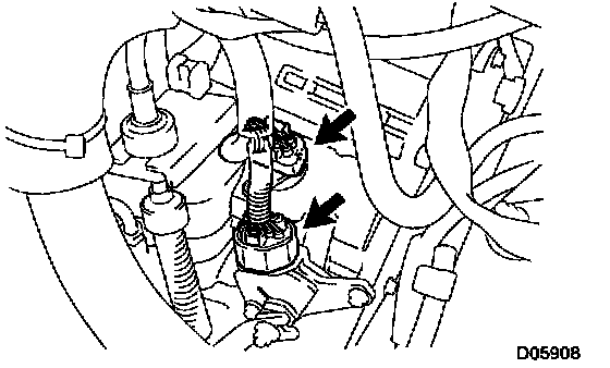
13. DISCONNECT SOLENOID CONNECTOR AND PARK/NEUTRAL POSITION SWITCH CONNECTOR
Disconnect the solenoid connector and park/neutral position switch connector.
14. DISCONNECT CONTROL CABLE
a) Remove the nut from the control shift lever.
Torque: 12 Nm (120 kgf-cm, 9 ft. lbs.)
b) Remove the clip and disconnect the control cable.
15. REMOVE BOLT AND DISCONNECT RADIATOR RESERVOIR
Torque: 4.9 Nm (50 kgf-cm, 43 inch lbs.)
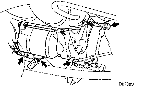
16. REMOVE STARTER
a) Remove the nut and wire, and disconnect the connector.
b) Remove the 2 bolts and starter.
Torque: 37 Nm (378 kgf-cm, 28 ft. lbs.)
17. REMOVE LH, RH, CENTER ENGINE UNDER COVERS
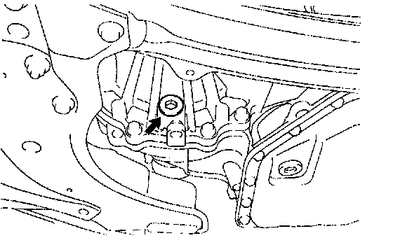
18. DRAIN ATF FROM FRONT DIFFERENTIAL CASE
Torque: 54 Nm (550 kgf-cm, 40 ft. lbs.)
19. REMOVE LH AND RH DRIVE SHAFTS
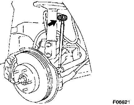
20. DISCONNECT LH AND RH STABILIZER BAR LINKS FROM SHOCK ABSORBER
Torque: 44 Nm (450 kgf-cm, 32 ft. lbs.)
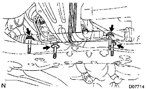
21. REMOVE 4 BOLTS AND DISCONNECT PS GEAR ASSEMBLY
HINT: Support the PS gear assembly securely.
Torque: 45 Nm (459 kgf-cm, 33 ft. lbs.)
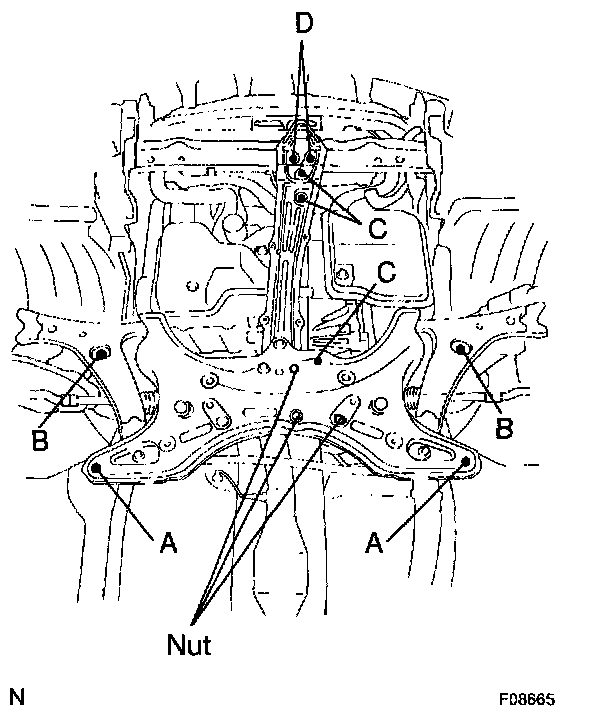
22. REMOVE SUSPENSION MEMBER
a) Remove the 9 bolts and 3 nuts.
Torque:
Bolt A: 157 Nm (1,601 kgf-cm, 116 ft. lbs.)
Bolt B: 113 Nm (1,152 kgf-cm, 83 ft. lbs.)
Bolt C: 52 Nm (530 kgf-cm, 38 ft. lbs.)
Bolt D: 39 Nm (398 kgf-cm, 29 ft. lbs.)
Nut: 52 Nm (530 kgf-cm, 38 ft. lbs.)
b) Remove the suspension member.
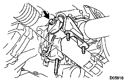
23. REMOVE ENGINE REAR MOUNTING INSULATOR
Remove the bolt and engine rear mounting insulator.
Torque: 87 Nm (890 kgf-cm, 64 ft. lbs.)
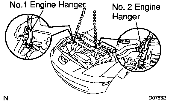
24. ATTACH ENGINE SLING DEVICE TO ENGINE HANGERS
a) Disconnect the 2 PCV hoses.
b) Install the No.1 and No.2 engine hangers in the correct direction.
Parts No.1
No.1 engine hanger: 12281-22021
No.2 engine hanger: 12281-15040 or 12281-15050
Bolt: 915112-131016
Torque: 38 Nm (387 kgf-cm, 28 ft. lbs.)
c) Attach the engine chain hoist to the engine hangers.
CAUTION: Do not attempt to hang the engine by hooking the chain to any other part.
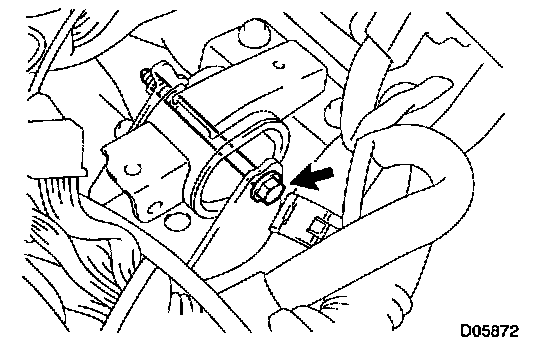
25. REMOVE UPPER SIDE ENGINE LEFT MOUNTING, NUT AND BOLT
Torque: 80 Nm (816 kgf-cm, 59 ft. lbs.)
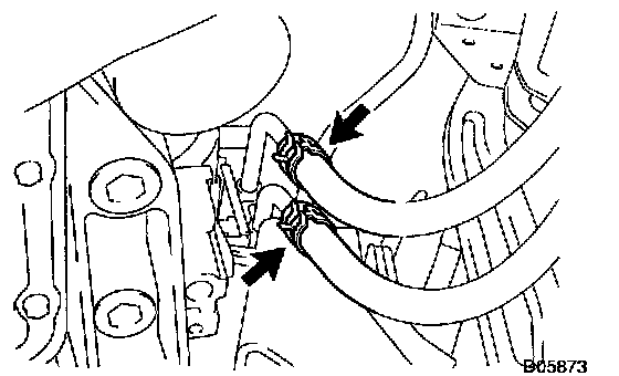
26. REMOVE OIL COOLER HOSE
Loosen the 2 clips and disconnect the 2 oil cooler hoses.
27. SUPPORT TRANSAXLE WITH A JACK
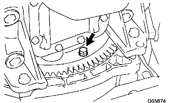
28. REMOVE TORQUE CONVERTER CLUTCH MOUNTING BOLT
a) Remove the hole plug.
b) Turn the crankshaft to gain access and remove the 6 bolts holding the crankshaft pulley set bolt with a wrench.
Torque: 25 Nm (250 kgf-cm, 18 ft. lbs.)
HINT: At the time of installation, please refer to the following item.
First install black colored bolt and then 5 other bolts.
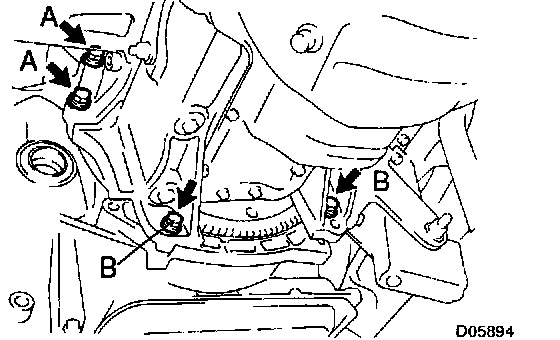
29. REMOVE TRANSAXLE ASSEMBLY
a) Remove the 4 bolts.
Torque:
A bolt: 46 Nm (470 kgf-cm, 34 ft. lbs.)
B bolt: 23 Nm (230 kgf-cm, 17 ft. lbs.)
b) Separate the transaxle from engine, and lower the transaxle.
INSTALLATION
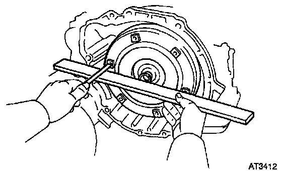
1. CHECK TORQUE CONVERTER CLUTCH INSTALLATION
Using calipers and a straight edge, measure the distance between the installed surface and the front surface of the transaxle housing.
Correct distance: More than 20.7 mm (0.185 inch)
2. TRANSAXLE INSTALLATION
Installation is in the reverse order of removal.
HINT:
- After installation, adjust the shift control cable and park/neutral position switch.
- Fill ATF and check the fluid level.
- Perform the test drive of the vehicle.
- Adjust the hood.