Engine Unit, Disassembly
ENGINE UNITComponents:
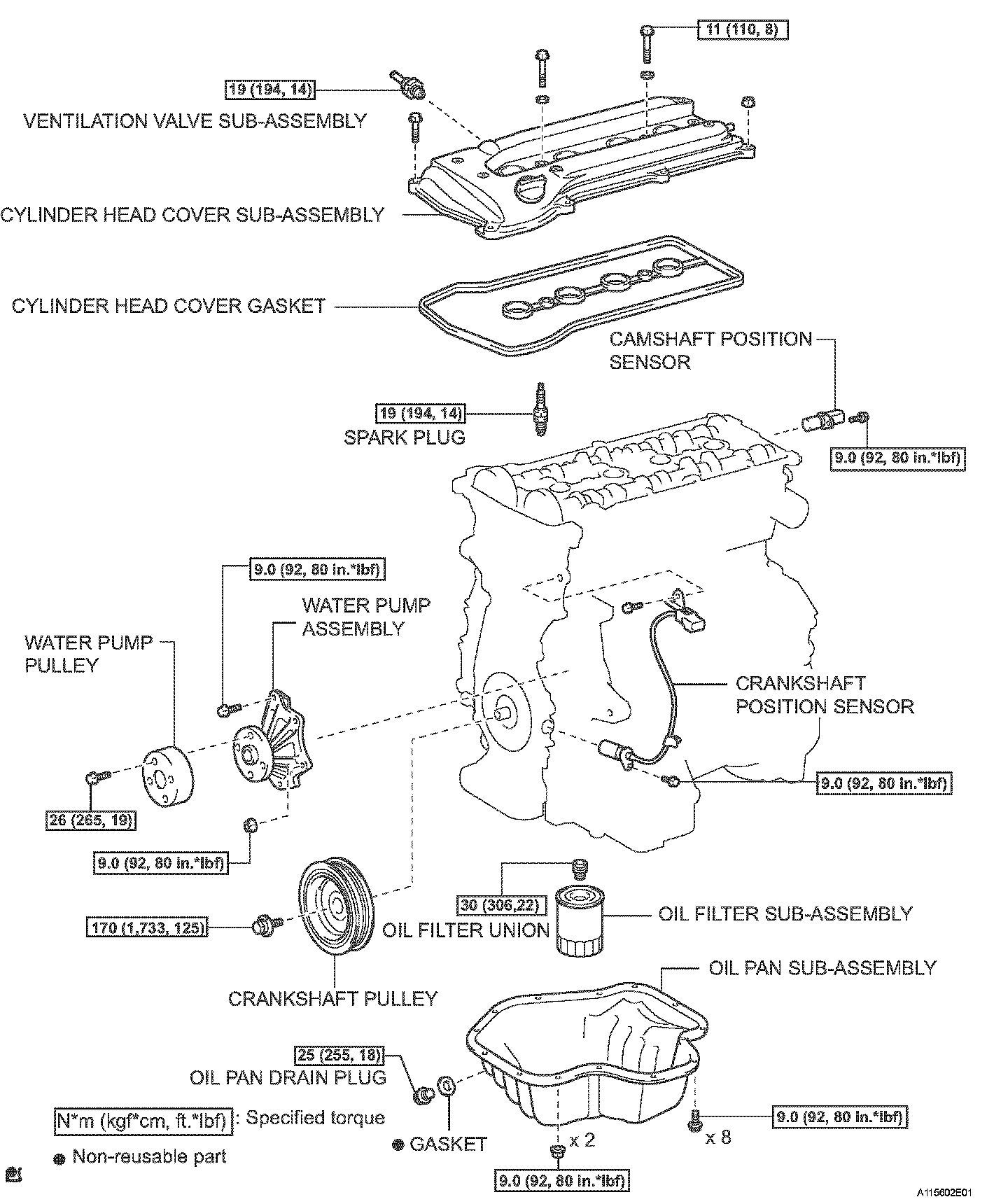
Components:
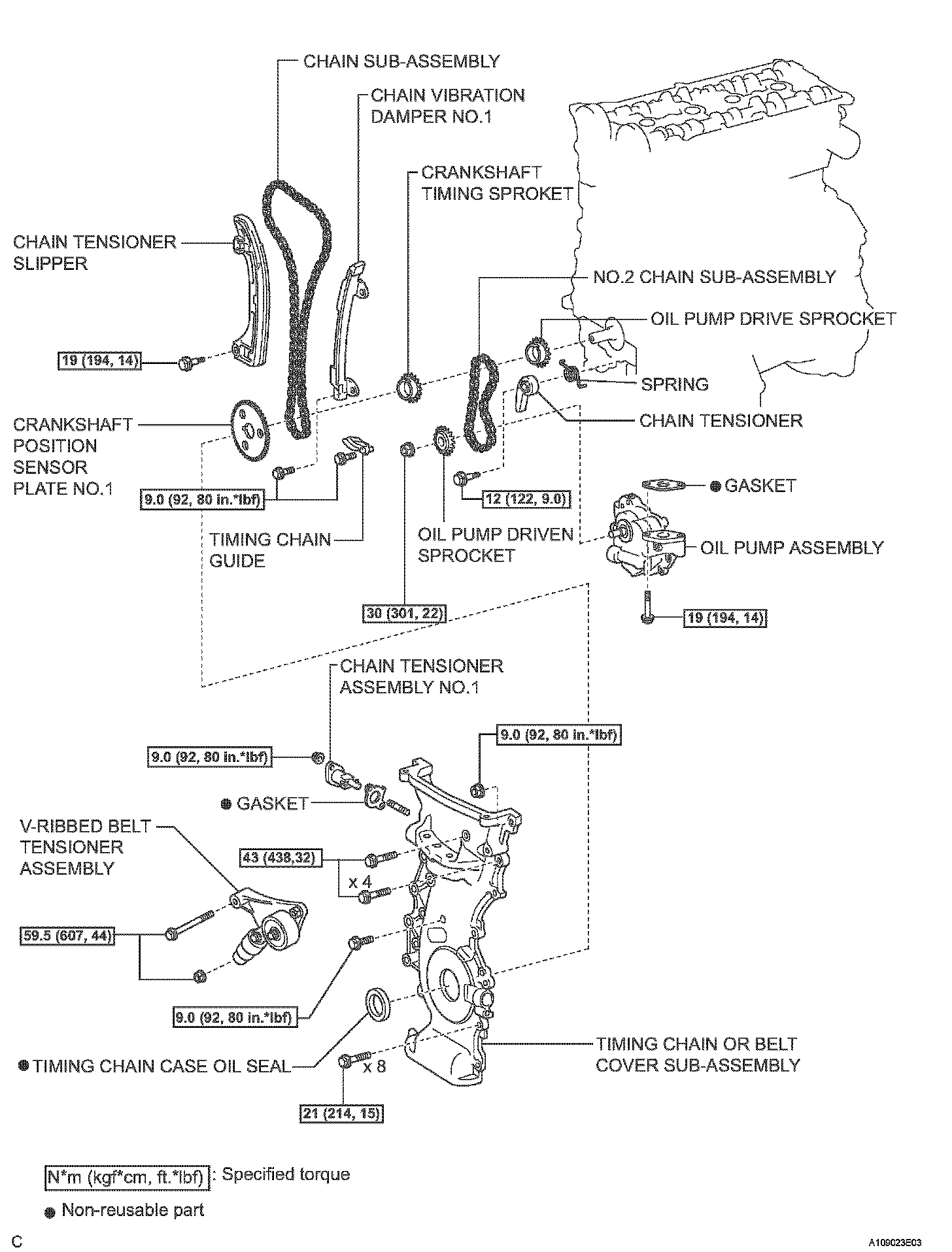
Components:
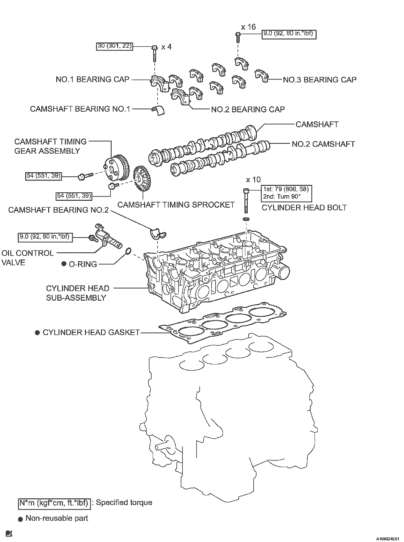
Components:
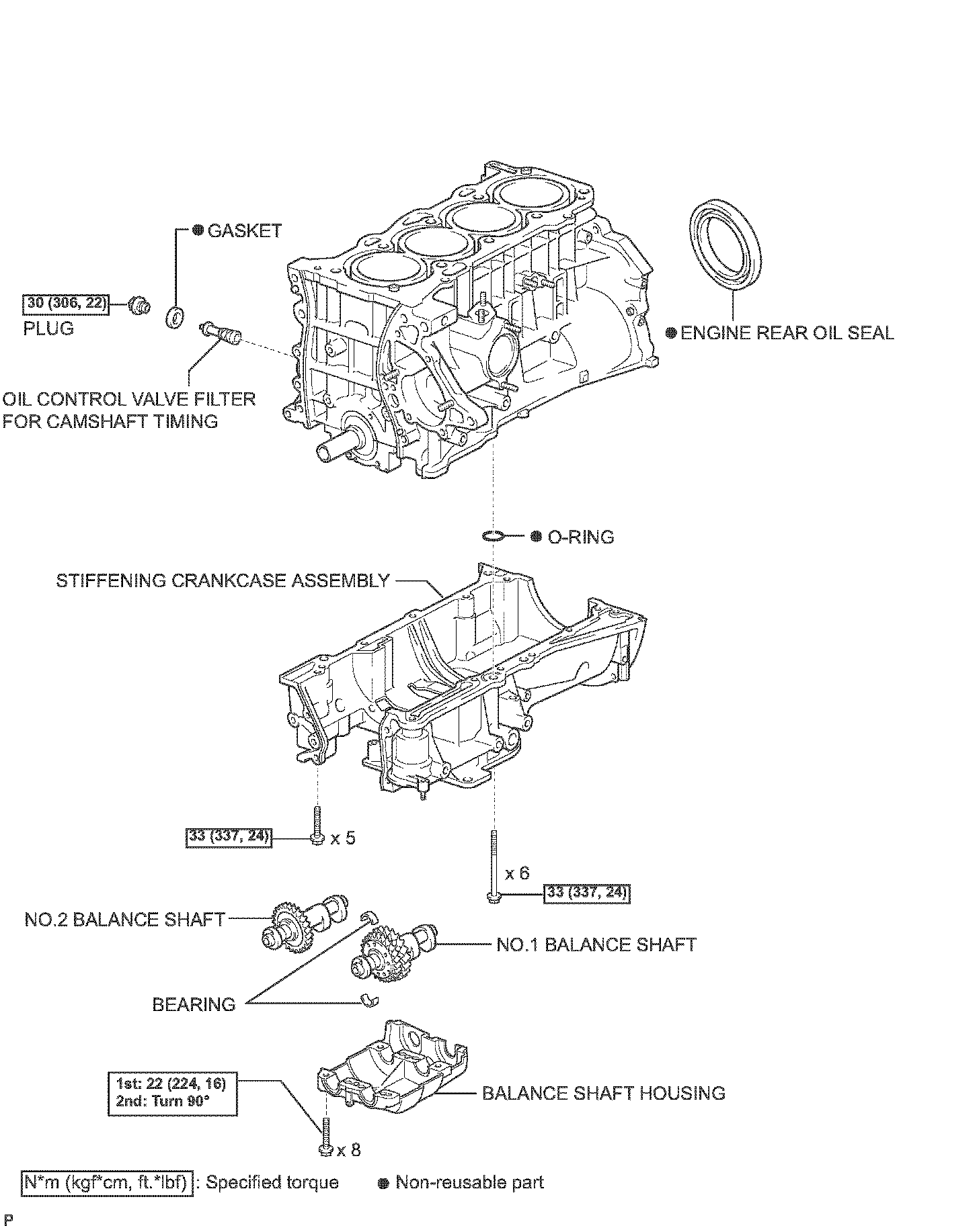
Components:
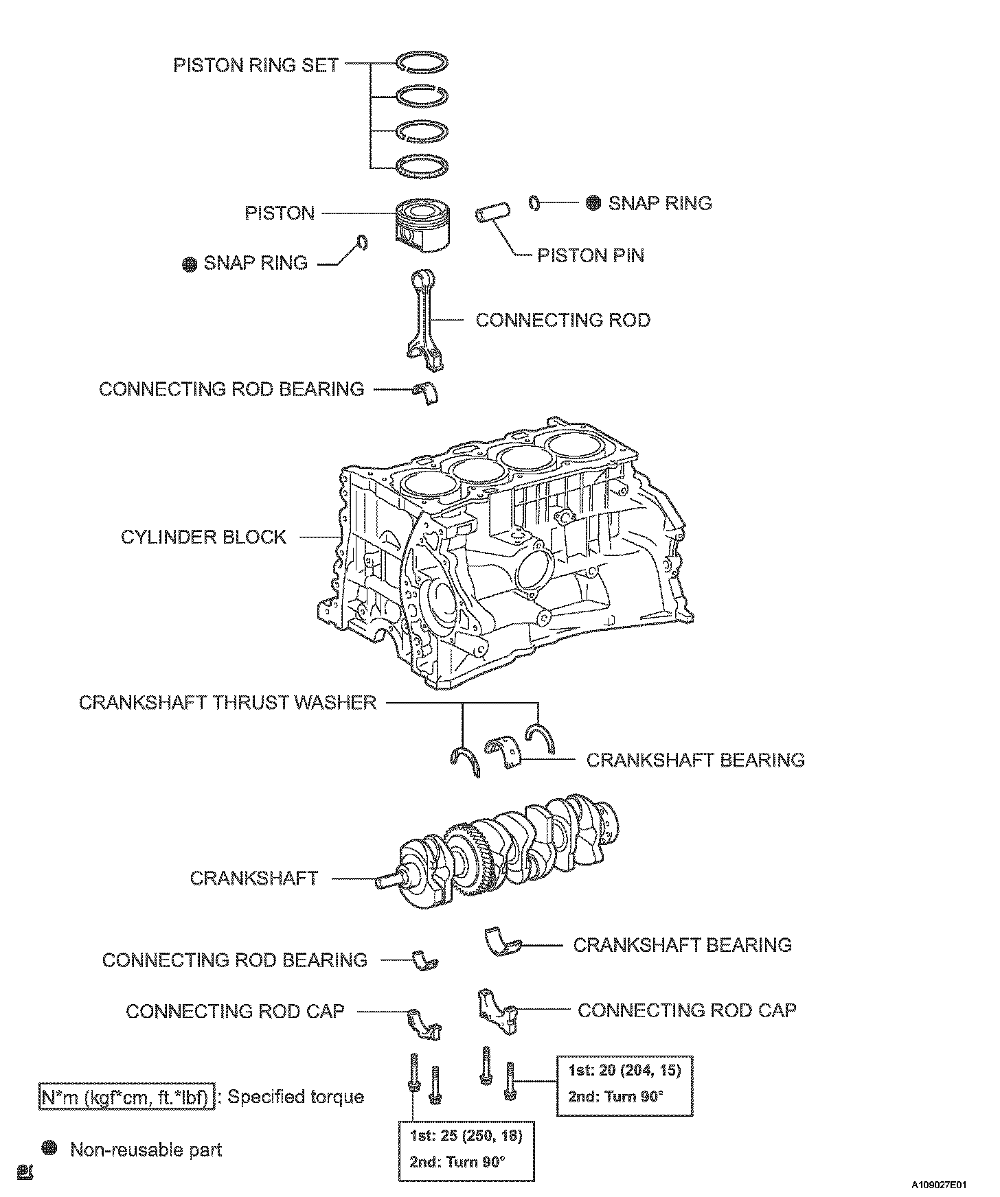
DISASSEMBLY
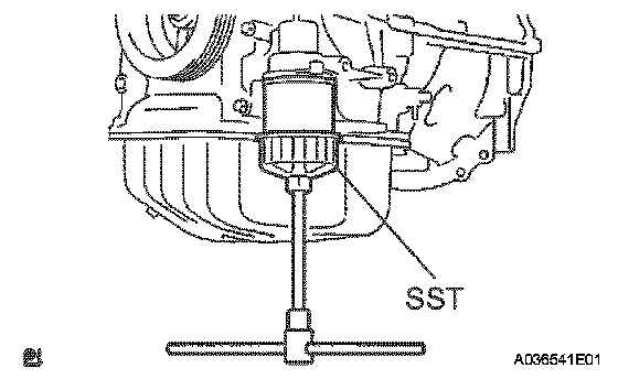
1. REMOVE OIL FILTER SUB-ASSEMBLY
a. Using SST, remove the oil filter.
SST 09228-06501
2. REMOVE OIL FILTER UNION
a. Using a 12 mm hexagon wrench, remove the union.
3. REMOVE OIL FILLER CAP SUB-ASSEMBLY
4. REMOVE VENTILATION VALVE SUB-ASSEMBLY
5. REMOVE SPARK PLUG
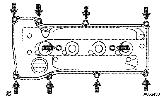
6. REMOVE CYLINDER HEAD COVER SUB-ASSEMBLY
a. Remove the 8 bolts, 2 nuts and cylinder head cover.
7. REMOVE CYLINDER HEAD COVER GASKET
8. REMOVE CRANKSHAFT POSITION SENSOR
9. REMOVE CRANKSHAFT PULLEY
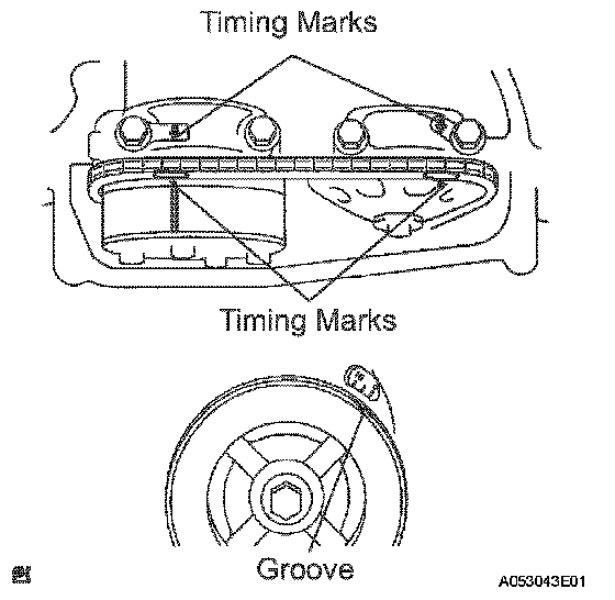
a. Turn the crankshaft pulley and align its groove with timing mark 0 of the timing chain cover.
b. Check that the timing marks of the camshaft timing gear and sprockets are aligned with the timing marks of bearing caps No. 1 and No. 2, as shown in the illustration.
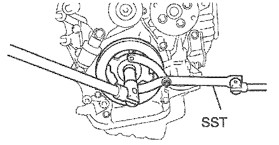
c. Remove the crankshaft pulley.
1 Using SST, fix the pulley and loosen the bolt.
SST 09960-10010 (09962-01000, 09963-01000)
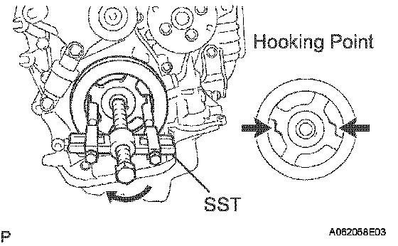
2 Using SST, remove the bolt and pulley.
SST 09950-40011 (09951-04010, 09952-04010, 09953-04030, 09954-04010, 09955-04041, 09957-04010, 91111-51014)
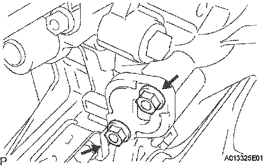
10. REMOVE NO.1 CHAIN TENSIONER ASSEMBLY
a. Remove the 2 nuts, chain tensioner and gasket.
NOTICE: Do not turn the crankshaft without the chain tensioner.
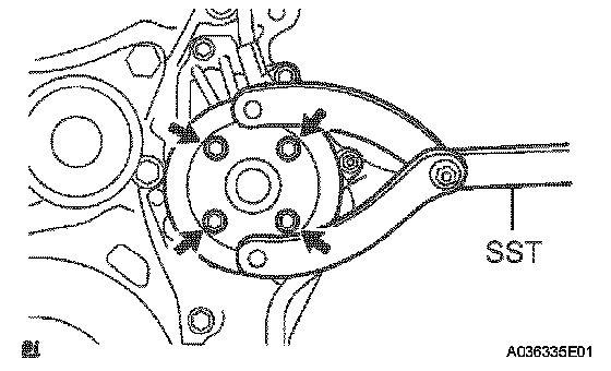
11. REMOVE WATER PUMP PULLEY
a. Using SST remove the water pump pulley.
SST 09960-10010 (09962-01000, 09963-00700)
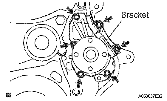
12. REMOVE WATER PUMP ASSEMBLY
a. Remove the 4 bolts, 2 nuts, bracket and water pump.
13. REMOVE OIL PAN DRAIN PLUG
14. REMOVE OIL PAN SUB-ASSEMBLY
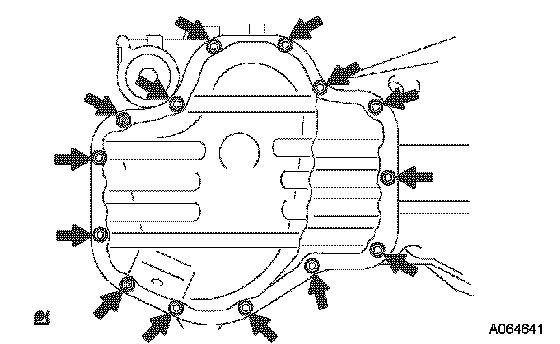
a. Remove the 12 bolts and 2 nuts.
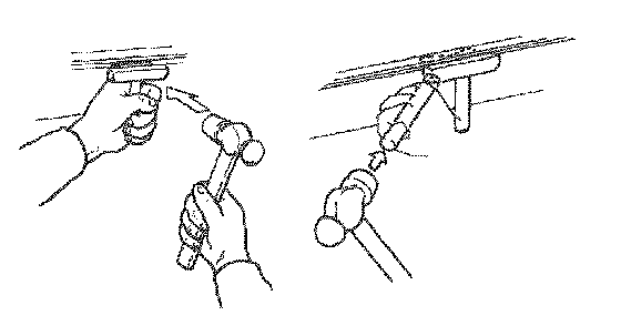
b. Insert the blade of SST between the crankcase and oil pan. Cut off applied sealer and remove the oil pan.
SST 09032-00100
NOTICE: Be careful not to damage the contact surface of the cylinder block and oil pan.
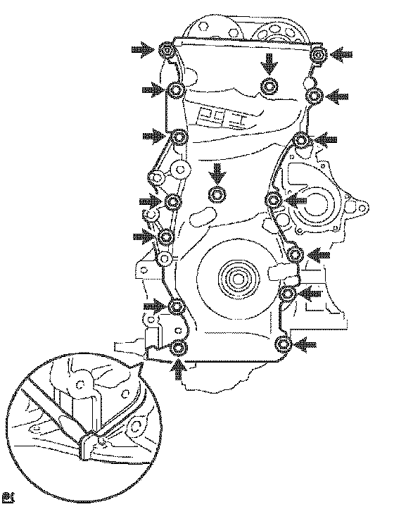
15. REMOVE TIMING CHAIN OR BELT COVER SUB-ASSEMBLY
a. Remove the 14 bolts and 2 nuts.
b. Remove the timing chain cover by prying between the timing chain cover and cylinder head or cylinder block with a screwdriver.
NOTICE: Be careful not to damage the contact surfaces of the timing chain cover, cylinder block and cylinder head.
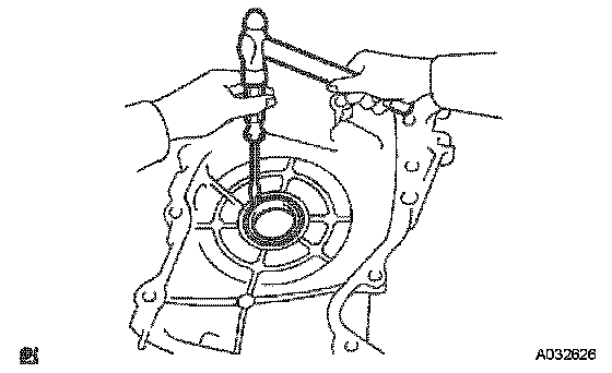
16. REMOVE TIMING GEAR CASE OR TIMING CHAIN CASE OIL SEAL
a. Using a screwdriver and a hammer, remove the oil seal.
17. REMOVE CRANKSHAFT POSITION SENSOR PLATE NO.1
18. REMOVE TIMING CHAIN GUIDE
19. REMOVE CHAIN TENSIONER SLIPPER
20. REMOVE CHAIN VIBRATION DAMPER NO.1
21. REMOVE CHAIN SUB-ASSEMBLY
22. REMOVE CRANKSHAFT TIMING GEAR OR SPROCKET
23. REMOVE NO.2 CHAIN SUB-ASSEMBLY
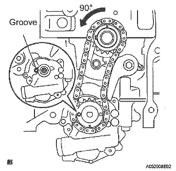
a. Turn the crankshaft counterclockwise by 90° and align the adjusting hole of the oil pump driven sprocket with the groove of the oil pump.
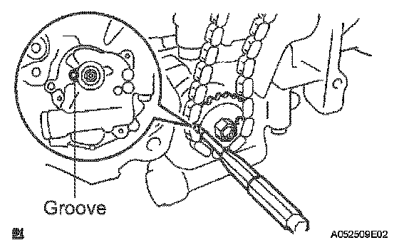
b. Put a bar ([diameter] 4 mm (0.157 inch)) in the adjusting hole of the oil pump driven sprocket to temporarily lock the sprocket in position. Remove the nut.
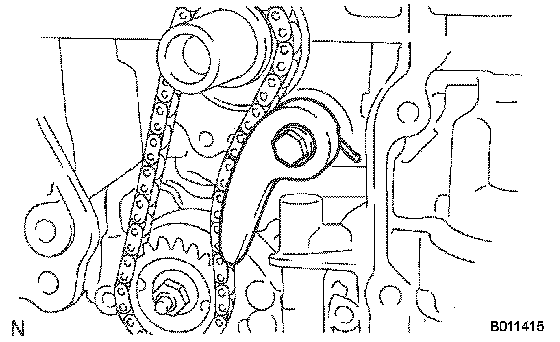
c. Remove the bolt, chain tensioner plate and spring.
d. Remove the oil pump drive sprocket, oil pump driven sprocket and chain.
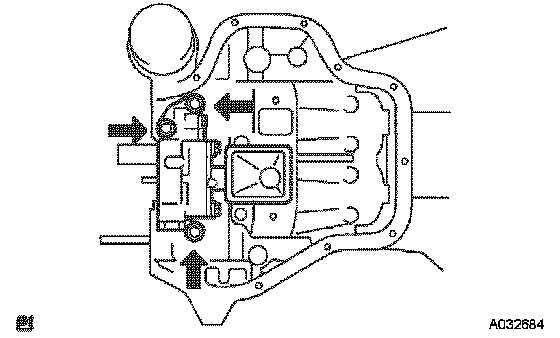
24. REMOVE OIL PUMP ASSEMBLY
a. Remove the 3 bolts, oil pump and gasket.

25. REMOVE NO.2 CAMSHAFT
a. Uniformly loosen and remove the camshaft's 10 bearing cap bolts in the sequence shown in the illustration. Then remove the 5 bearings.
b. Remove the camshaft.
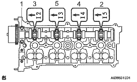
26. REMOVE CAMSHAFT
a. Uniformly loosen and remove the camshaft's 10 bearing cap bolts in the sequence shown in the illustration. Then remove the 5 bearings.
b. Remove the camshaft.
27. REMOVE CAMSHAFT BEARING NO.1
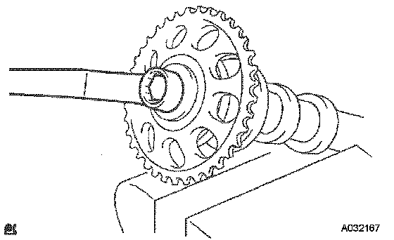
28. REMOVE CAMSHAFT TIMING SPROCKET
a. Fix the camshaft in a vise and remove the camshaft timing sprocket.
NOTICE: Be careful not to damage the camshaft.
29. REMOVE CAMSHAFT TIMING GEAR ASSEMBLY
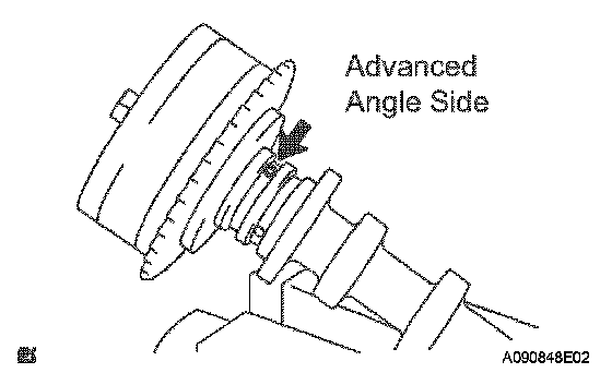
a. Fix the camshaft in a vise, and make sure that the camshaft timing gear does not move.
b. Cover all the oil ports with vinyl tape except the advanced angle side shown in the illustration.
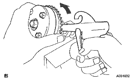
c. Using an air gun, apply about 150 kPa (1.5 kgf/cm2, 21 psi) of air pressure to the port on the advanced angle side.
CAUTION: Some oil spraying will occur. Contain the spray with a shop rag.
HINT: This operation releases the lock pin for the extreme retarded angle lock.
d. Under the condition above, check that the camshaft timing gear can be turned by hand to the advanced angle side (counterclockwise), the direction of the arrow in the illustration.
Standard: Can be turned
HINT: The camshaft timing gear will turn to the advanced angle side without applying force by hand depending on the force of the air pressure applied. Also, if applying pressure to the oil path is difficult as a result of air leakage from the port, the lock-pin may be difficult to release.
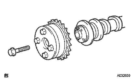
e. Remove the fringe bolt from the camshaft timing gear.
NOTICE:
^ Be sure not to remove the other 4 bolts.
^ If planning to reuse the camshaft timing gear, release the straight pin lock first, and then install the gear.
30. REMOVE CAMSHAFT BEARING NO.2
31. REMOVE CAMSHAFT TIMING OIL CONTROL VALVE ASSEMBLY
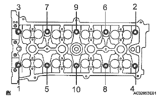
32. REMOVE CYLINDER HEAD SUB-ASSEMBLY
a. Using a 10 mm bi-hexagon wrench, uniformly loosen the 10 bolts in the sequence shown in the illustration. Remove the 10 cylinder head bolts and plate washers.
NOTICE:
^ Be careful not to drop washers into the cylinder head.
^ Head warpage or cracking could result from removing bolts in an incorrect order.
33. REMOVE CYLINDER HEAD GASKET
34. REMOVE CYLINDER BLOCK WATER COCK SUB-ASSEMBLY
35. REMOVE OIL CONTROL VALVE FILTER
a. Using a 6 mm socket hexagon wrench, remove the plug and filter.
36. REMOVE W/HEAD TAPER SCREW PLUG NO.1
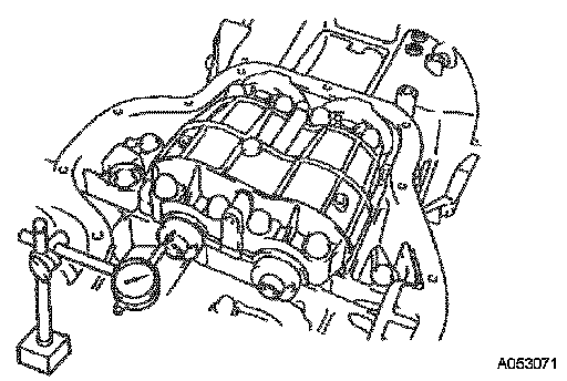
37. INSPECT BALANCE SHAFT THRUST CLEARANCE
a. Using a dial indicator, measure the thrust clearance while moving the balance shaft back and forth.
Specified thrust clearance: 0.050 to 0.090 mm (0.0020 to 0.0035 inch)
If the thrust clearance is greater than the maximum, replace the balance shaft housing and bearings. If necessary, replace the balance shaft.
38. INSPECT BALANCE SHAFT OIL CLEARANCE
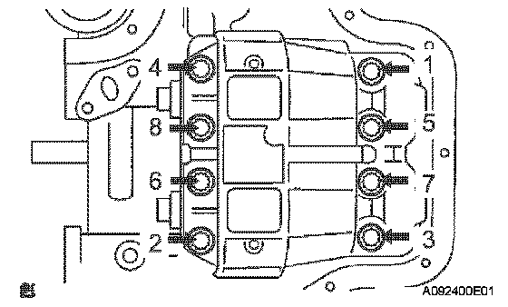
a. Uniformly loosen and remove the 8 bolts in the sequence shown in the illustration.
NOTICE: Be careful not to damage the contact surfaces of the balance shaft housing and crankcase.
HINT: Keep the lower bearing and balance shaft housing together.
b. Lift out the No. 1 and No. 2 balance shafts.
HINT: Keep the upper bearing with the crankcase.
c. Clean each bearing and journal.
d. Check each bearing and journal for pitting and scratches.
If a bearing or journal is damaged, replace the bearings. If necessary, replace the balance shaft.
e. Place the No. 1 and No. 2 balance shafts on the crankcase.
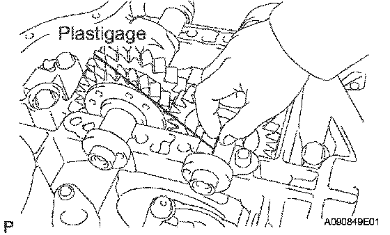
f. Lay a strip of Plastigage across each journal, and install the balance shaft housing.
g. Apply a light coat of engine oil on the threads and under the heads of the balance shaft housing bolts.
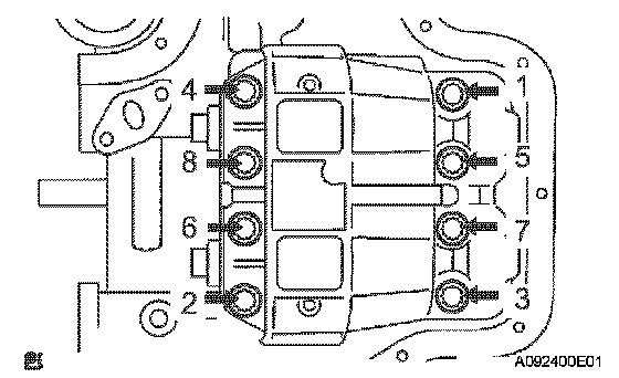
h. Uniformly tighten the 8 bolts in the sequence shown in the illustration.
Torque: 22 Nm (220 kgf-cm, 16 ft. lbs.)
HINT: The balance shaft housing bolts are tightened in 2 progressive steps.
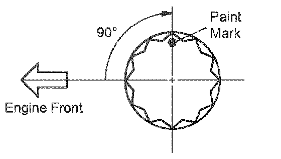
i. Mark the front side of each balance shaft housing bolt head with paint.
j. Retighten the bolts by 90° as shown in the illustration.
k. Check that the paint marks are now at a 90° angle to the front.
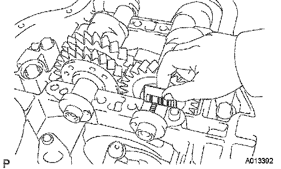
l. Remove the balance shaft housing, and measure the Plastigage at its widest point.
Specified oil clearance: 0.004 to 0.031 mm (0.0002 to 0.0012 inch)
If the clearance is greater than the maximum, replace the bearing. If necessary, replace the balance shaft.
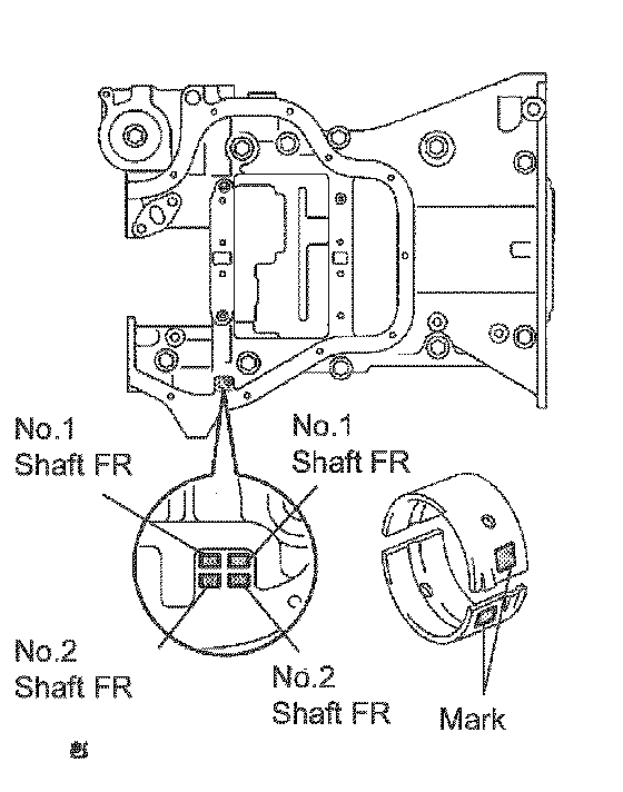
m. Completely remove the plastigage after the inspection.
HINT: If replacing a bearing, replace it with one that has the same number as the stiffening crankcase. There are 3 sizes of standard bearings: 1, 2 and 3.
Balance Shaft Housing Journal Bore Diameter:

Balance shaft journal diameter: 22.985 to 23.000 mm (0.9049 to 0.9055 inch)
Standard Bearing Center Wall Thickness:

n. Completely remove the Plastigage after the inspection.
39. REMOVE BALANCE SHAFT
40. REMOVE BALANCE SHAFT BEARING NO.1
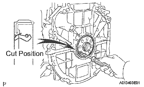
41. REMOVE ENGINE REAR OIL SEAL
a. Using a knife, cut off the oil seal lip.
b. Using a screwdriver with its tip taped, pry out the oil seal.
NOTICE: After the removal, check the crankshaft for damage. If it is damaged, smooth the surface with 400-grit sandpaper.
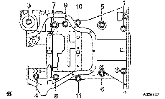
42. REMOVE STEERING CRANKCASE ASSEMBLY
a. Uniformly loosen and remove the 11 bolts in the sequence shown in the illustration.
b. Using a screwdriver, remove the crankcase by prying between the crankcase and cylinder block.
NOTICE: Be careful not to damage the contact surfaces of the crankcase and cylinder block.
c. Remove the O-ring from the cylinder block.
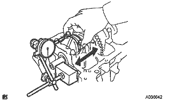
43. INSPECT CONNECTING ROD THRUST CLEARANCE
a. Using a dial indicator, measure the thrust clearance while moving the connecting rod back and forth.
Specified thrust clearance: 0.160 to 0.362 mm (0.0063 to 0.0143 inch)
If the thrust clearance is greater than the maximum, replace the connecting rod assembly(s). If necessary, replace the crankshaft.
44. INSPECT CONNECTING ROD OIL CLEARANCE
HINT: The connecting rod cap bolts are tightened in 2 progressive steps.
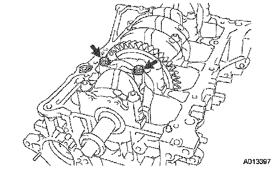
a. Check that the matchmarks on the connecting rod and cap are aligned to ensure the correct reassembly.
HINT: The matchmarks on the connecting rods and caps are for ensuring the correct reassembly.
b. Using a 12 mm socket wrench, uniformly loosen the 2 bolts.
c. Using the 2 removed connecting rod cap bolts, remove the connecting rod cap and lower bearing by wiggling the connecting rod cap right and left.
HINT: Keep the lower bearing inserted to the connecting rod cap.
d. Clean the crank pin and bearing.
e. Check the crank pin and bearing for pitting and scratches.
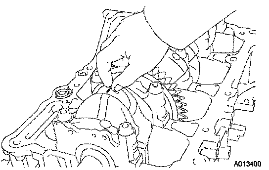
f. Lay a strip of Plastigage on the crank pin.
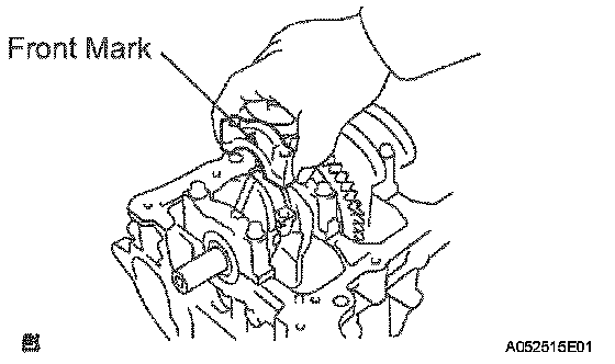
g. Check that the front mark of the connecting rod cap is facing in the correct direction.
h. Apply a light coat of engine oil on the threads and under the heads of the connecting rod cap bolts.
i. Install the connecting cap.
NOTICE: Do not turn the crankshaft.
j. Remove the 2 bolts and connecting rod cap.
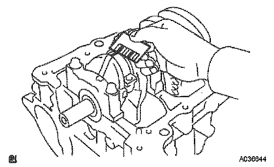
k. Measure the Plastigage at its widest point.
Specified oil clearance: 0.024 to 0.080 mm (0.0009 to 0.0031 inch)
If the crank pin or bearing is damaged, replace the bearings. If necessary, replace the crankshaft.
HINT: If replacing a bearing, replace it with one that has the same number as the connecting rod. There are 3 sizes of standard bearings: 1, 2 and 3.
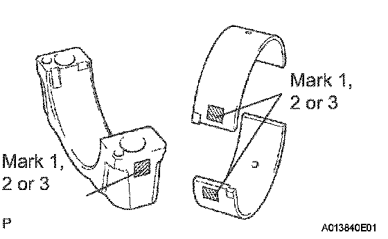
1 Check the number mark shown in the illustration.
Standard Bearing Center Wall Thickness:

l. Completely remove the Plastigage.
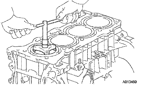
45. REMOVE PISTON AND CONNECTING ROD
a. Using a ridge reamer, remove all the carbon from the top of the cylinder.
b. Push the piston, connecting rod assembly and upper bearing through the top of the cylinder block.
HINT:
^ Keep the bearing, connecting rod and cap together.
^ Arrange the piston and connecting rod assemblies in the correct order.
46. REMOVE CONNECTING ROD BEARING

47. REMOVE PISTON RING SET
a. Using a piston ring expander, remove the 2 compression rings.
b. Remove the 2 side rails and oil ring by hand.
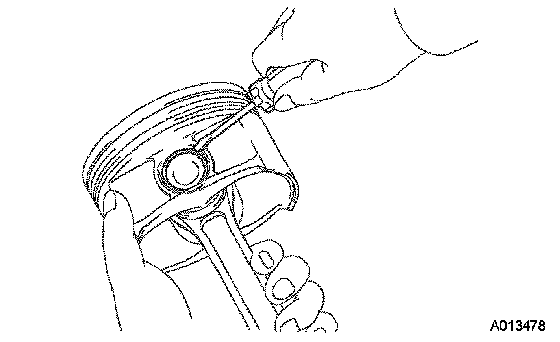
48. REMOVE PISTON PIN HOLE SNAP RING
a. Using a small screwdriver, pry out the 2 snap rings.
49. REMOVE PISTON
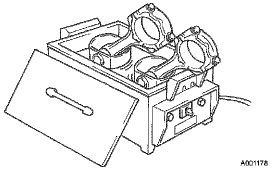
a. Gradually heat the piston to approximately 80 to 90°C (176 to 194°F).
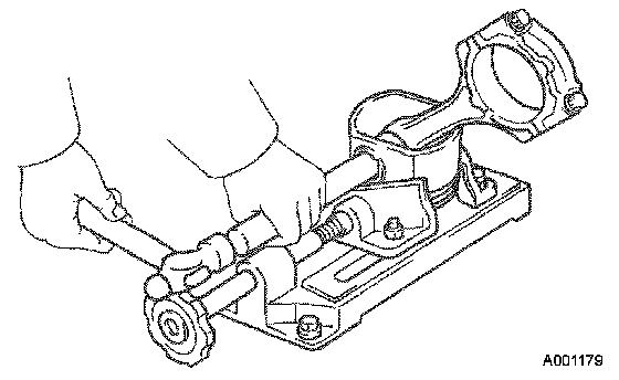
b. Using a plastic-faced hammer and brass bar, lightly tap out the piston pin and remove the connecting rod.
HINT:
^ The piston and pin are a matched set.
^ Arrange the pistons, pins, rings, connecting rods and bearings in the correct order.
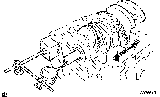
50. INSPECT CRANKSHAFT THRUST CLEARANCE
a. Using a dial indicator, measure the thrust clearance while prying the crankshaft back and forth with a screwdriver.
Specified thrust clearance: 0.040 to 0.300 mm (0.0016 to 0.0118 inch)
If the thrust clearance is greater than the maximum, replace the thrust washers as a set.
Thrust washer thickness: 1.930 to 1.980 mm (0.0760 to 0.0780 inch)
51. INSPECT CRANKSHAFT OIL CLEARANCE
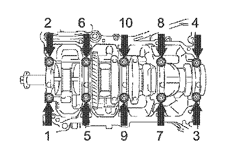
a. Uniformly loosen and remove the 10 main bearing cap bolt in the sequence shown in the illustration.
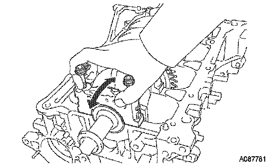
b. Use 2 removed main bearing cap bolts to remove the 5 main bearing caps and 5 lower bearings.
NOTICE: Insert the bolts into one of the caps. Ease the cap out by gently pulling up and applying force toward the front and back side of the cylinder block, as shown in the illustration. Take care not to damage the contact surfaces of the cap and cylinder block.
HINT:
^ Keep the lower bearing and main bearing cap together.
^ Arrange the main bearing caps in correct order.
c. Lift out the crankshaft.
HINT: Keep the upper bearings together with the cylinder block.
d. Clean each main journal and bearing.
e. Check each main journal and bearing for pitting and scratches.
If the journal or bearing is damaged, replace the bearings.
If necessary, replace the crankshaft.
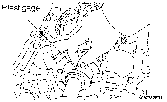
f. Place the crankshaft on the cylinder block.
g. Lay a strip of Plastigage across each journal.
h. Install the main bearing caps.
HINT: Do not turn the crankshaft.
i. Remove the main bearing cap.
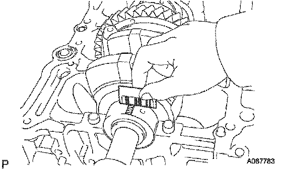
j. Measure the Plastigage at its widest point.
Standard oil clearance: 0.008 to 0.024 mm (0.00031 to 0.00094 inch)
If the oil clearance is greater than the maximum, replace the bearings. If necessary, replace the crankshaft.
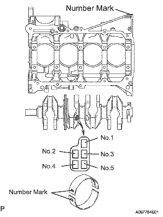
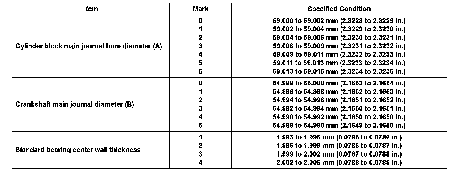
k. If using a standard bearing, replace it with one having the same number. If the number of the bearing cannot be determined, select the correct bearing by adding together the numbers imprinted on the cylinder block and crankshaft, and then selecting the bearing according to the chart. There are 4 sizes of standard bearings: 1, 2, 3, and 4.
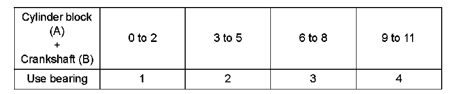
HINT: EXAMPLE Cylinder block 4 (A) + Crankshaft 3 (B) = Total number 7 (Use bearing 3)
Reference:
l. Completely remove the Plastigage.
52. REMOVE CRANKSHAFT
a. Lift out the crankshaft.
b. Remove the 5 upper main bearings and 2 thrust washers from the cylinder block.
HINT: Arrange the main bearings and thrust washers in the correct order.
53. REMOVE CRANKSHAFT THRUST WASHER UPPER
54. REMOVE CRANKSHAFT BEARING
HINT: Arrange the bearings in the correct order.
55. REMOVE CRANKSHAFT BEARING NO.2
HINT: Arrange the main bearings and thrust washers in the correct order.
56. REMOVE STUD BOLT
57. CLEAN CYLINDER BLOCK
NOTICE: If the cylinder is washed at high temperatures, the cylinder liner sticks out beyond the cylinder block. Always wash the cylinder block at a temperature of 45°C (113°F) or less.