Valve Body: Service and Repair
VALVE BODY ASSEMBLYCOMPONENTS:
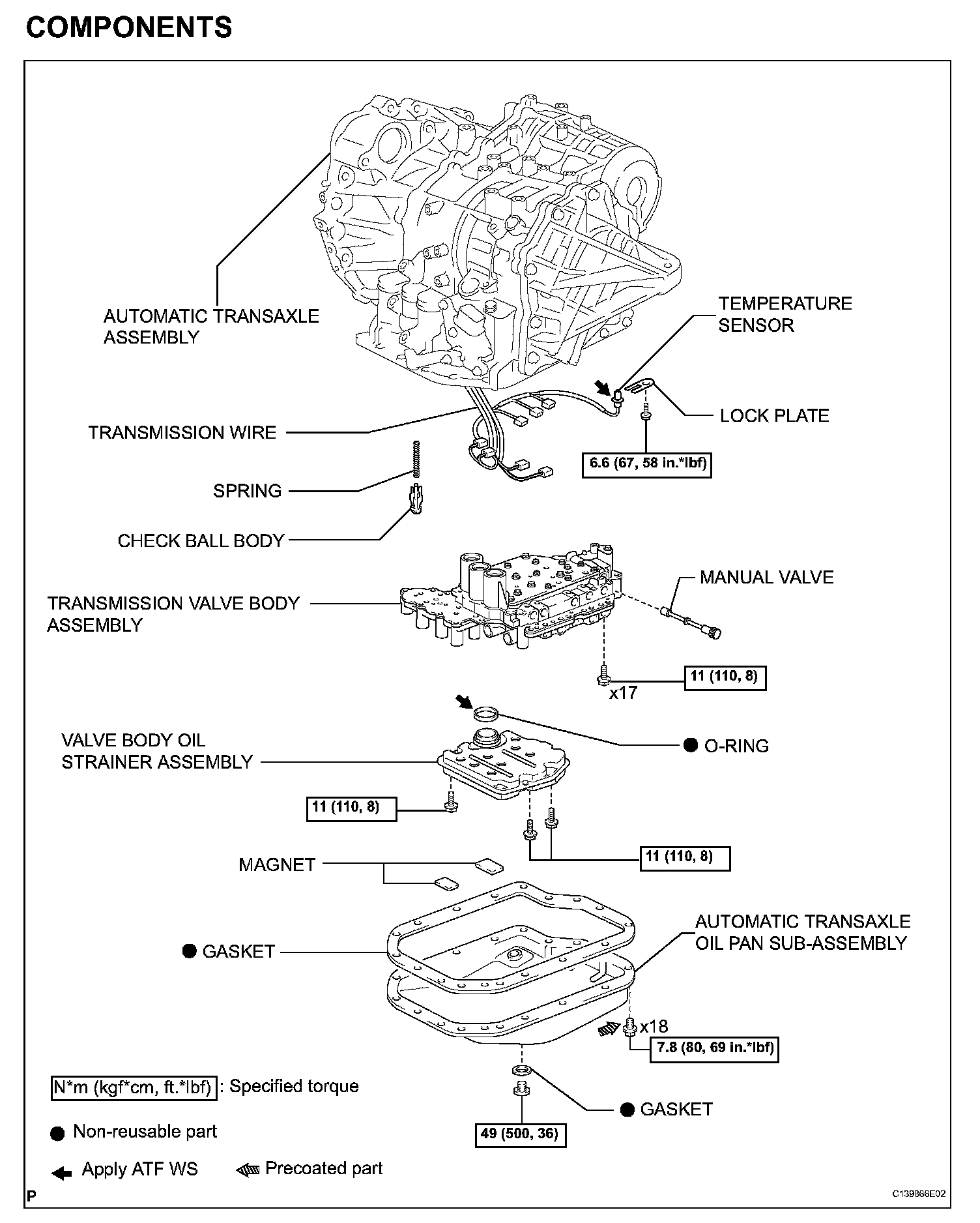
REMOVAL
1. REMOVE AUTOMATIC TRANSAXLE ASSEMBLY
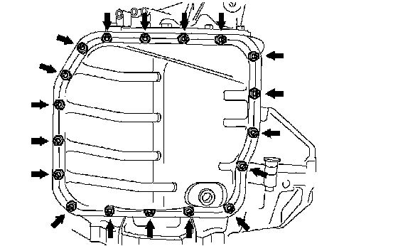
2. REMOVE AUTOMATIC TRANSAXLE OIL PAN SUBASSEMBLY
(a) Remove the 18 bolts, oil pan and gasket.
NOTICE: Some fluid will remain in the oil pan. Remove all the pan bolts, and carefully remove the oil pan assembly.
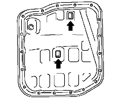
(b) Remove the 2 magnets from the oil pan.
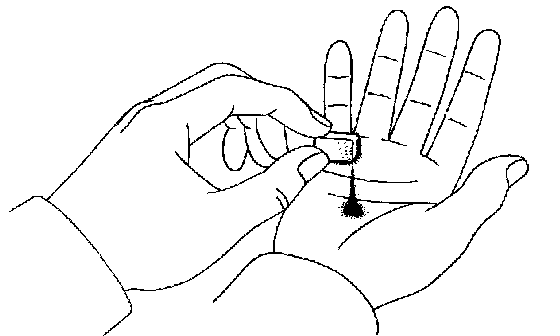
(c) Examine particles in the pan.
(1) Collect any steel chips with the removed magnets. Look carefully at the chips and particles in the pan and on the magnets to see the type of wear which might be found in the transaxle.
Result:
Steel (magnetic): bearing, gear and plate wear
Brass (non-magnetic): bearing wear
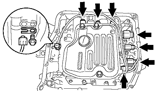
3. DISCONNECT TRANSMISSION WIRE
(a) Disconnect the 7 shift solenoid valve connectors.
(b) Remove the bolt and lock plate, and disconnect the ATF temperature sensor.
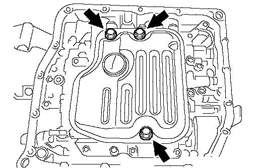
4. REMOVE VALVE BODY OIL STRAINER ASSEMBLY
(a) Remove the 3 bolts and oil strainer.
NOTICE: Be careful that some fluid will come out of the oil strainer.
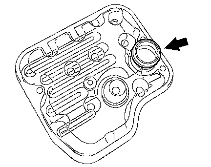
(b) Remove the O-ring from the oil strainer.
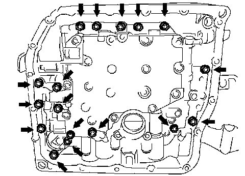
5. REMOVE TRANSMISSION VALVE BODY ASSEMBLY
(a) Support the valve body assembly and remove the 17 bolts and the valve body assembly.
NOTICE: Be careful not to drop the check ball, spring and accumulator piston.
(b) Remove the check ball body and spring.
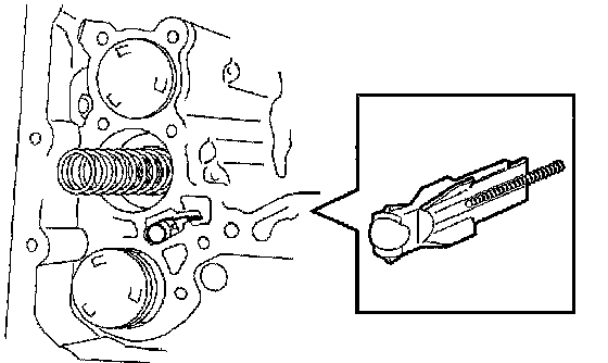
6. REMOVE MANUAL VALVE
(a) Remove the manual valve from the valve body assembly.
INSTALLATION
1. INSTALL MANUAL VALVE
(a) Install the manual valve to the valve body assembly.
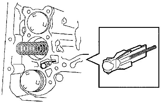
2. INSTALL TRANSMISSION VALVE BODY ASSEMBLY
(a) Install the spring and check ball body.
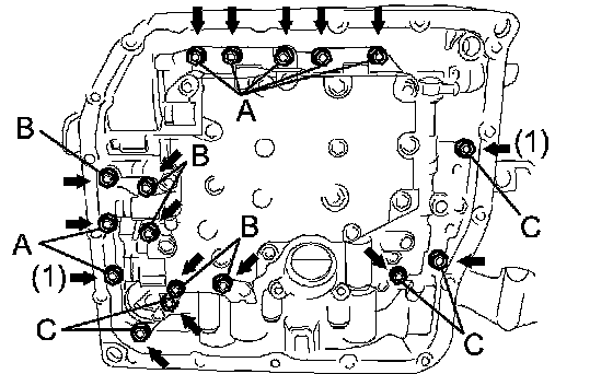
(b) Align the groove of the manual valve with the pin of the lever.
(c) Install the valve body with the 17 bolts.
Torque: 11 Nm (110 kgf-cm, 8 ft. lbs.)
NOTICE:
^ Push the valve body against the accumulator piston spring and the check ball body to install it.
^ First, temporarily tighten the bolts marked by
(1) in the illustration because they are positioning bolts.
Bolt length:
Bolt A: 25 mm (0.984 inch)
Bolt B: 57 mm (2.244 inch)
Bolt C: 41 mm (1.614 inch)
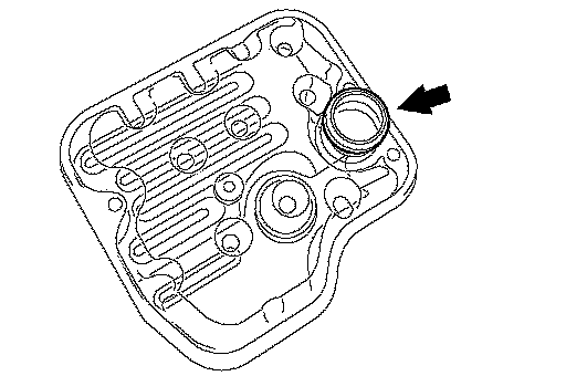
3. INSTALL VALVE BODY OIL STRAINER ASSEMBLY
(a) Coat a new O-ring with ATF WS.
(b) Install the O-ring to the oil strainer.
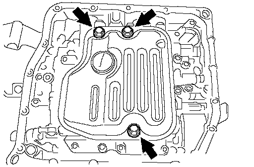
(c) Install the oil strainer with the 3 bolts.
Torque: 11 Nm (110 kgf-cm, 8 ft. lbs.)
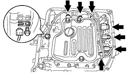
4. INSTALL TRANSMISSION WIRE
(a) Coat the O-ring with ATF WS.
(b) Install the ATF temperature sensor with the lock plate and bolt.
Torque: 6.6 Nm (67 kgf-cm, 58 inch lbs.)
(c) Connect the 7 shift solenoid valve connectors.
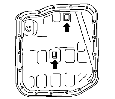
5. INSTALL AUTOMATIC TRANSAXLE OIL PAN SUBASSEMBLY
(a) Install the 2 magnets in the oil pan.
(b) Apply adhesive or equivalent to new 18 bolts.
Adhesive: Toyota Genuine Adhesive 1344, Three Bond 1344 or Equivalent
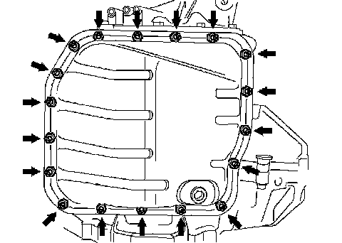
(c) Using a new gasket, install the oil pan to the transaxle case with the 18 bolts.
Torque: 7.8 Nm (80 kgf-cm, 69 inch lbs.)
NOTICE: Since the bolts should be seal bolts, apply adhesive to the bolts and tighten them within 10 minutes of application.
6. CONNECT CABLE TO NEGATIVE BATTERY TERMINAL
Torque: 6.9 Nm (70 kgf-cm, 61 inch lbs.)
7. INSTALL AUTOMATIC TRANSAXLE ASSEMBLY