Air Conditioning Unit (For Hatchback)
Air Conditioning Unit (for Hatchback):
Air Conditioning Unit (for Hatchback):
Air Conditioning Unit (for Hatchback):
Air Conditioning Unit (for Hatchback):
Air Conditioning Unit (for Hatchback):
Air Conditioning Unit (for Hatchback):
Air Conditioning Unit (for Hatchback):
Air Conditioning Unit (for Hatchback):
Air Conditioning Unit (for Hatchback):
Air Conditioning Unit (for Hatchback):
Air Conditioning Unit (for Hatchback):
Air Conditioning Unit (for Hatchback):
Air Conditioning Unit (for Hatchback):
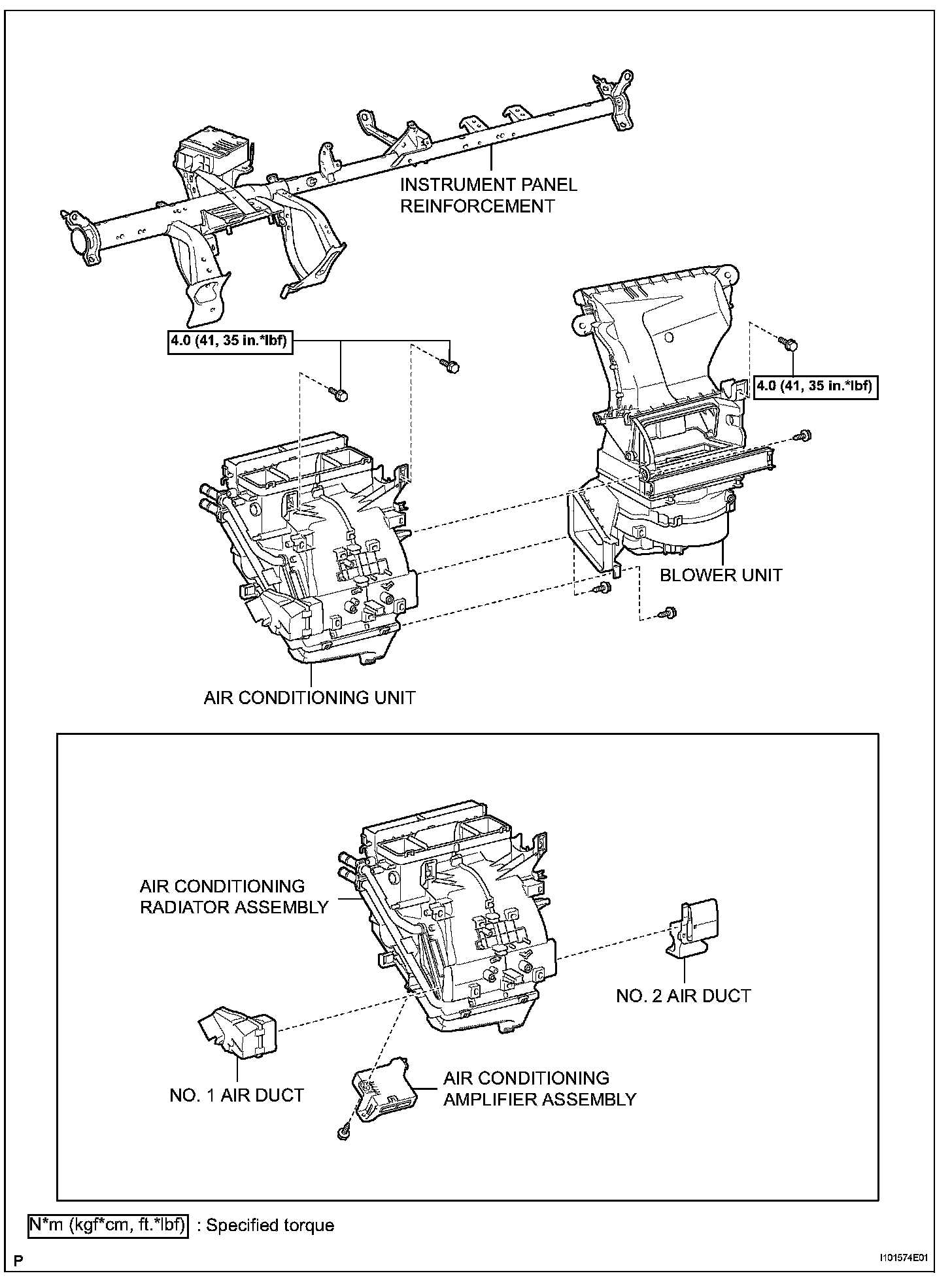
Air Conditioning Unit (for Hatchback):
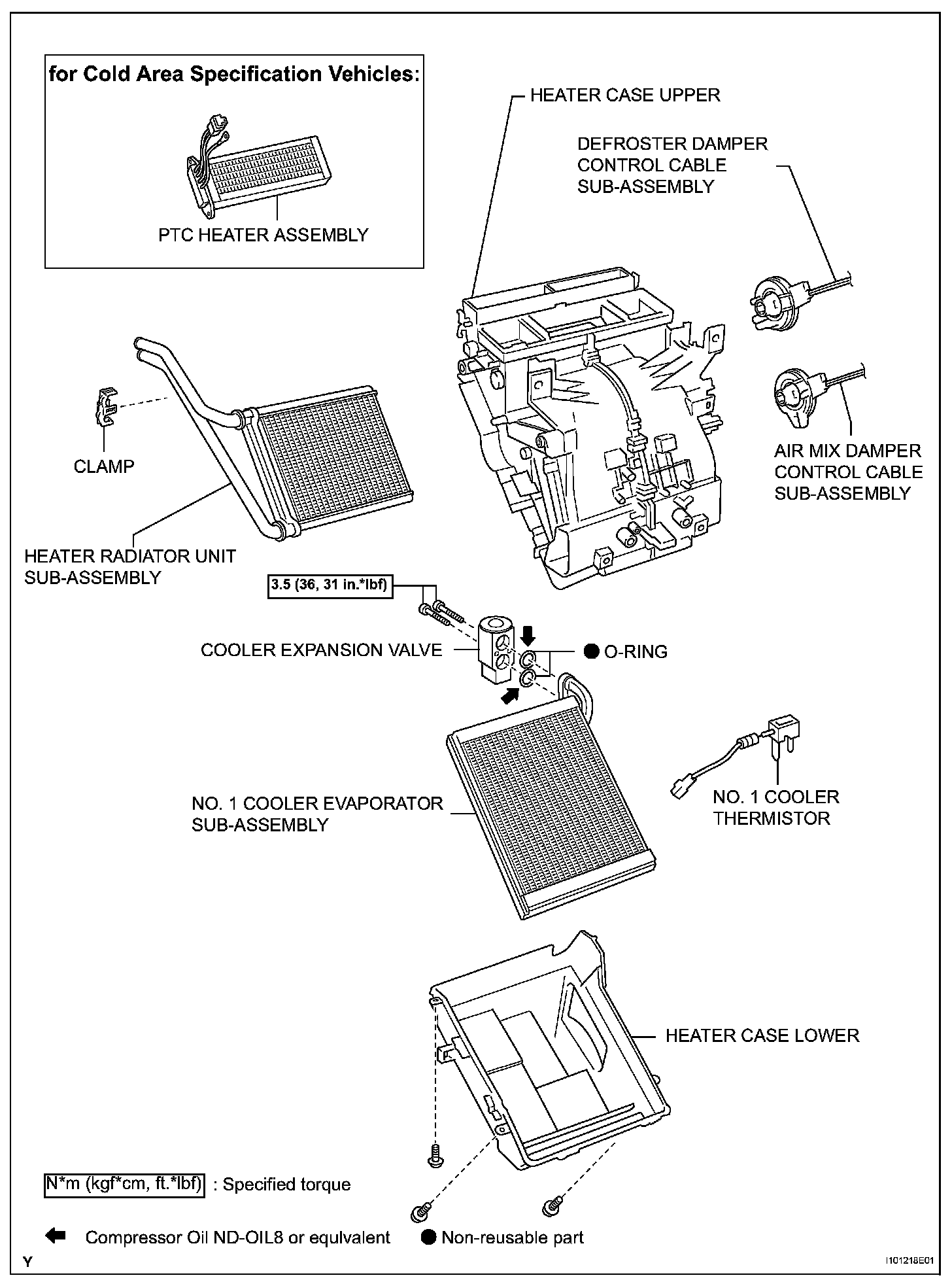
AIR CONDITIONING UNIT (for Hatchback)
REMOVAL
CAUTION: Some of these service operations affect the SRS airbag system. Refer to Restraint Systems Service Precautions before servicing.
HINT: Use the same procedure for both the RH and LH sides.
1. DISCONNECT CABLE FROM NEGATIVE BATTERY TERMINAL
Wait for at least 90 seconds after disconnecting the cable to prevent the airbag from working.
2. DISCHARGE REFRIGERANT FROM REFRIGERATION SYSTEM
3. DRAIN ENGINE COOLANT
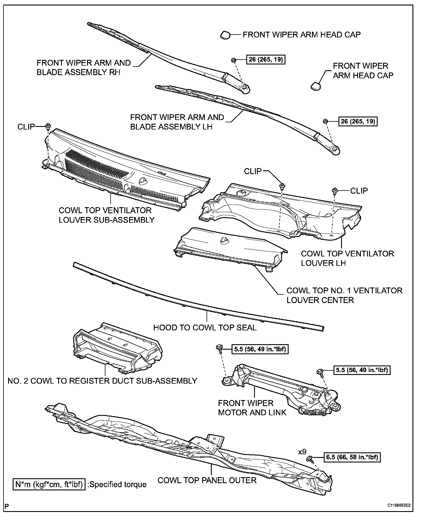
4. REMOVE FRONT WIPER ARM HEAD CAP
5. REMOVE FRONT WIPER ARM AND BLADE ASSEMBLY LH
6. REMOVE FRONT WIPER ARM AND BLADE ASSEMBLY RH
7. REMOVE HOOD TO COWL TOP SEAL
8. REMOVE COWL TOP VENTILATOR LOUVER SUB-ASSEMBLY
9. REMOVE COWL TOP VENTILATOR LOUVER LH
10. REMOVE FRONT WIPER MOTOR AND LINK
11. REMOVE NO. 2 COWL TO REGISTER DUCT SUB-ASSEMBLY
12. REMOVE COWL TOP PANEL OUTER
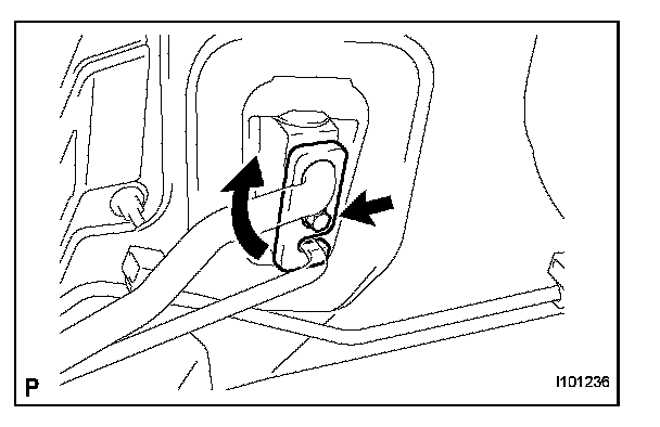
13. DISCONNECT SUCTION TUBE SUB-ASSEMBLY
a. Remove the bolt.
b. Turn the hook type connector clockwise and disconnect the suction tube.
c. Remove the O-ring from the suction tube.
NOTE: Seal the openings of the disconnected parts using vinyl tape to prevent moisture and foreign matter from entering.
14. DISCONNECT LIQUID TUBE SUB-ASSEMBLY
a. Disconnect the liquid tube.
b. Remove the O-ring from liquid tube.
NOTE: Seal the opening of the disconnected parts using vinyl tape to prevent moisture and foreign matter from entering.

15. DISCONNECT HEATER WATER OUTLET HOSE A (FROM HEATER UNIT)
a. Using pliers, grip the claws of the clip, slide the clip and disconnect the heater water outlet hose from the heater unit.
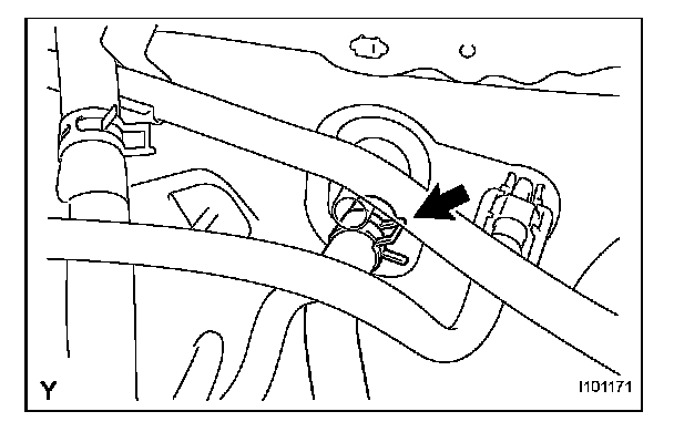
16. DISCONNECT HEATER WATER INLET HOSE A
a. Using pliers, grip the claws of the clip, slide the clip and disconnect the heater water inlet hose from the heater unit.
17. BOLTS, SCREWS AND NUTS TABLE
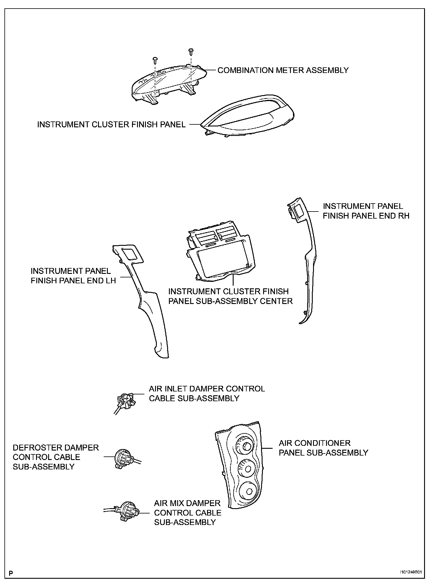
18. REMOVE INSTRUMENT PANEL FINISH PANEL END LH
19. REMOVE INSTRUMENT PANEL FINISH PANEL END RH
20. REMOVE INSTRUMENT CLUSTER FINISH PANEL
21. REMOVE COMBINATION METER ASSEMBLY
22. REMOVE INSTRUMENT CLUSTER FINISH PANEL SUB-ASSEMBLY CENTER
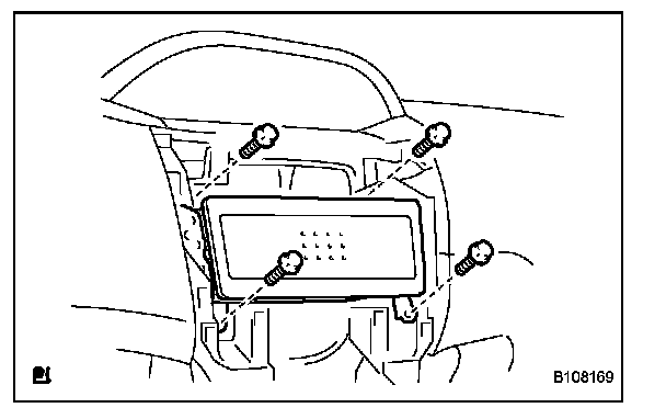
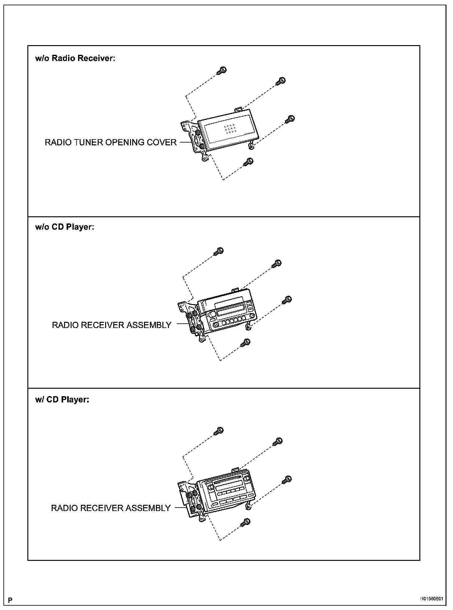
23. REMOVE RADIO TUNER OPENING COVER (w/o Radio Receiver)
a. Remove the 4 bolts and the radio tuner opening cover.
24. REMOVE RADIO RECEIVER ASSEMBLY
25. REMOVE AIR CONDITIONER PANEL SUB-ASSEMBLY
26. DISCONNECT AIR MIX DAMPER CONTROL CABLE SUB-ASSEMBLY
27. DISCONNECT DEFROSTER DAMPER CONTROL CABLE SUB-ASSEMBLY
28. DISCONNECT AIR INLET DAMPER CONTROL CABLE SUB-ASSEMBLY
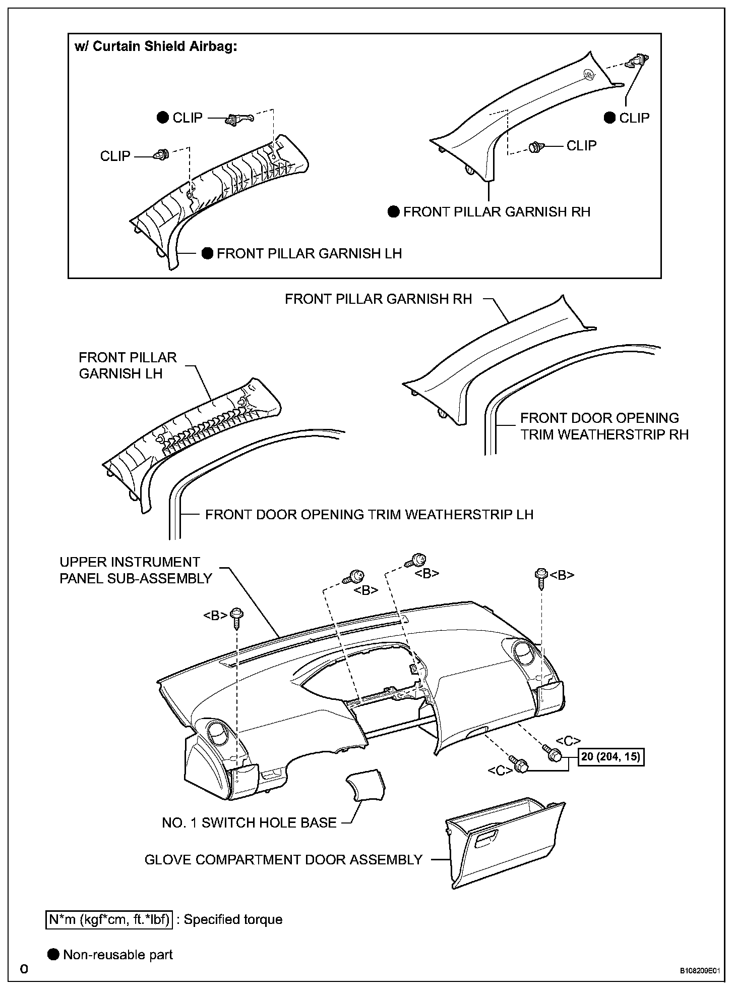
29. REMOVE FRONT DOOR OPENING TRIM WEATHERSTRIP RH
30. REMOVE FRONT DOOR OPENING TRIM WEATHERSTRIP LH
31. REMOVE FRONT PILLAR GARNISH RH
32. REMOVE FRONT PILLAR GARNISH LH
33. REMOVE NO. 1 SWITCH HOLE BASE
34. REMOVE GLOVE COMPARTMENT DOOR ASSEMBLY
35. REMOVE UPPER INSTRUMENT PANEL SUB-ASSEMBLY
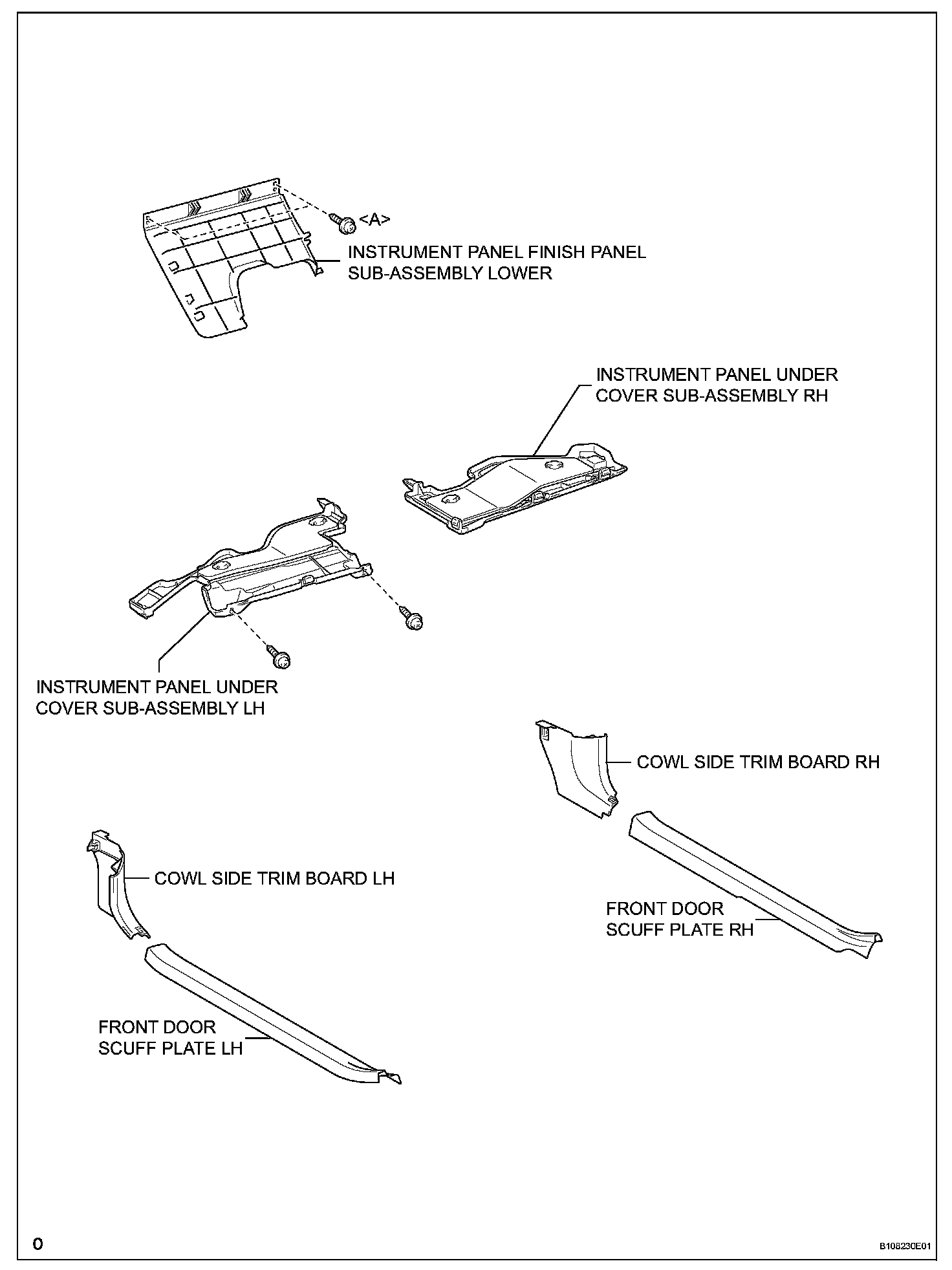
36. REMOVE FRONT DOOR SCUFF PLATE RH
37. REMOVE FRONT DOOR SCUFF PLATE LH
38. REMOVE INSTRUMENT PANEL UNDER COVER SUB-ASSEMBLY RH
39. REMOVE INSTRUMENT PANEL UNDER COVER SUB-ASSEMBLY LH
40. REMOVE COWL SIDE TRIM BOARD RH
41. REMOVE COWL SIDE TRIM BOARD LH
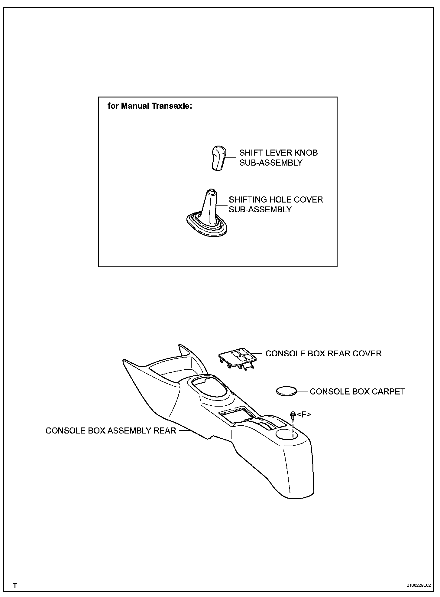
42. REMOVE SHIFT LEVER KNOB SUB-ASSEMBLY (for Manual Transaxle)
43. REMOVE SHIFTING HOLE COVER SUB-ASSEMBLY (for Manual Transaxle)
44. REMOVE CONSOLE BOX REAR COVER
45. REMOVE CONSOLE BOX CARPET
46. REMOVE CONSOLE BOX ASSEMBLY REAR
47. REMOVE INSTRUMENT PANEL FINISH PANEL SUB-ASSEMBLY LOWER
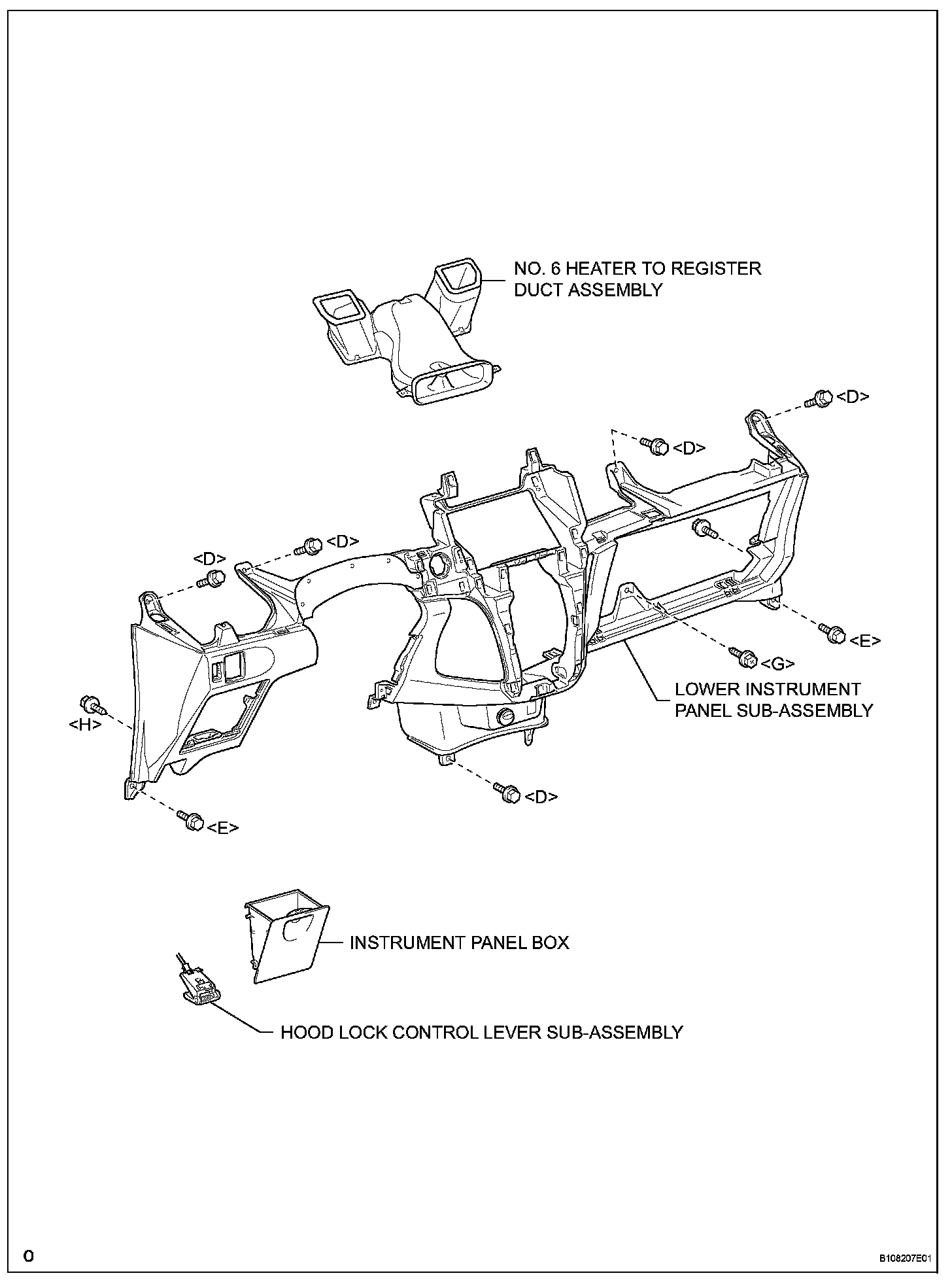
48. REMOVE INSTRUMENT PANEL BOX
49. REMOVE NO. 6 HEATER TO REGISTER DUCT ASSEMBLY
50. DISCONNECT ANTENNA CORD SUB-ASSEMBLY
51. SEPARATE HOOD LOCK CONTROL LEVER SUB-ASSEMBLY
52. REMOVE LOWER INSTRUMENT PANEL SUB-ASSEMBLY
53. POSITION FRONT WHEELS FACING STRAIGHT AHEAD
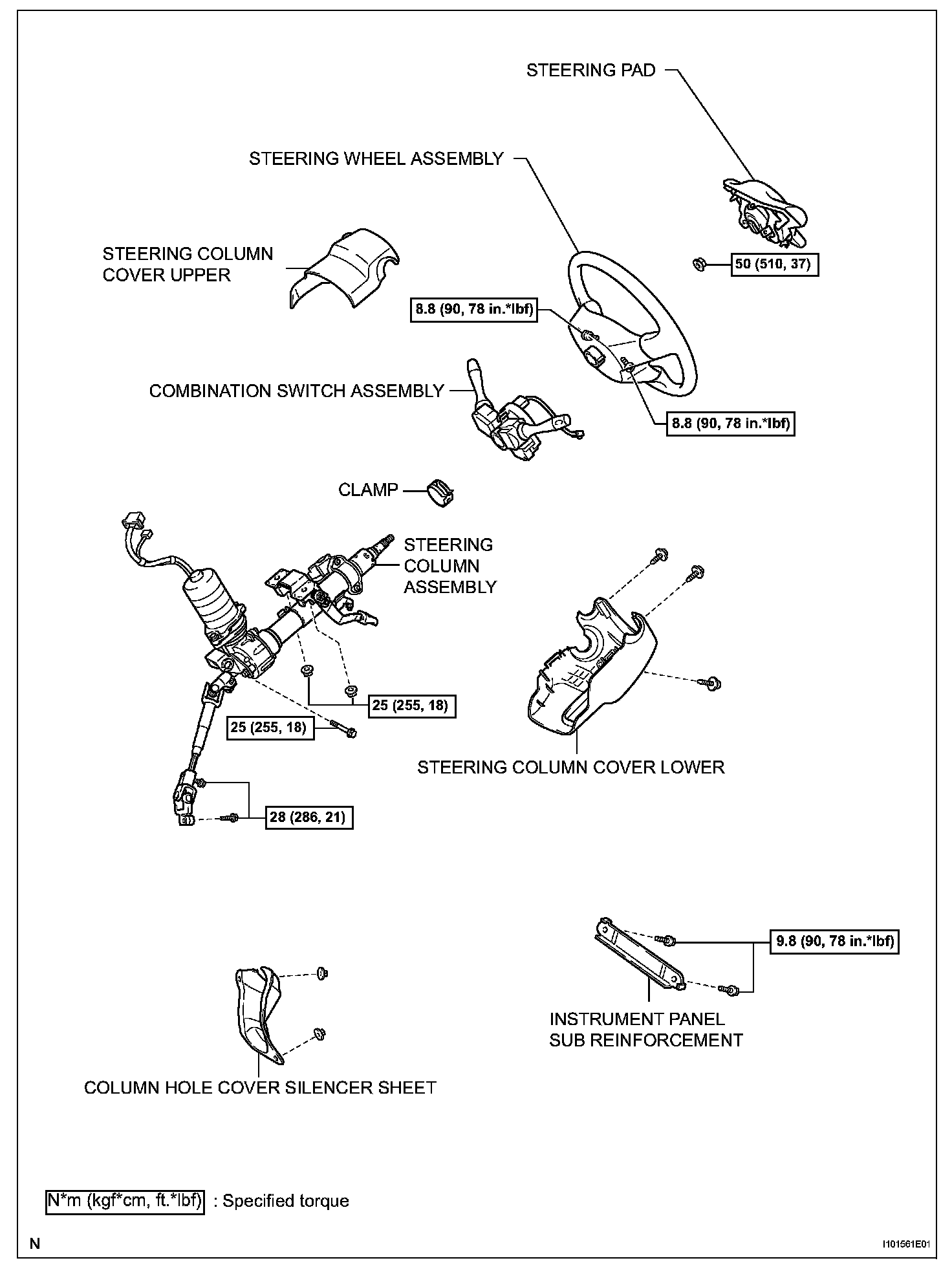
54. REMOVE STEERING PAD
55. REMOVE STEERING WHEEL ASSEMBLY
56. REMOVE STEERING COLUMN COVER
57. REMOVE COMBINATION SWITCH ASSEMBLY
58. DISCONNECT POWER STEERING ECU
59. REMOVE INSTRUMENT PANEL SUB REINFORCEMENT
60. REMOVE COLUMN HOLE COVER SILENCER SHEET
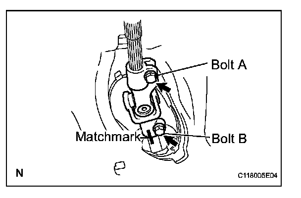
61. SEPARATE STEERING SLIDING YOKE SUB-ASSEMBLY
a. Place matchmarks on the sliding yoke of the steering intermediate shaft and the power steering link.
b. Loosen bolt A, remove bolt B and separate the steering yoke.
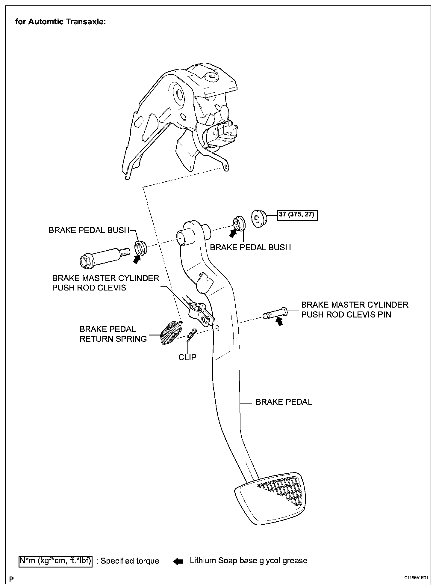
62. REMOVE BRAKE PEDAL (for Automatic Transaxle)
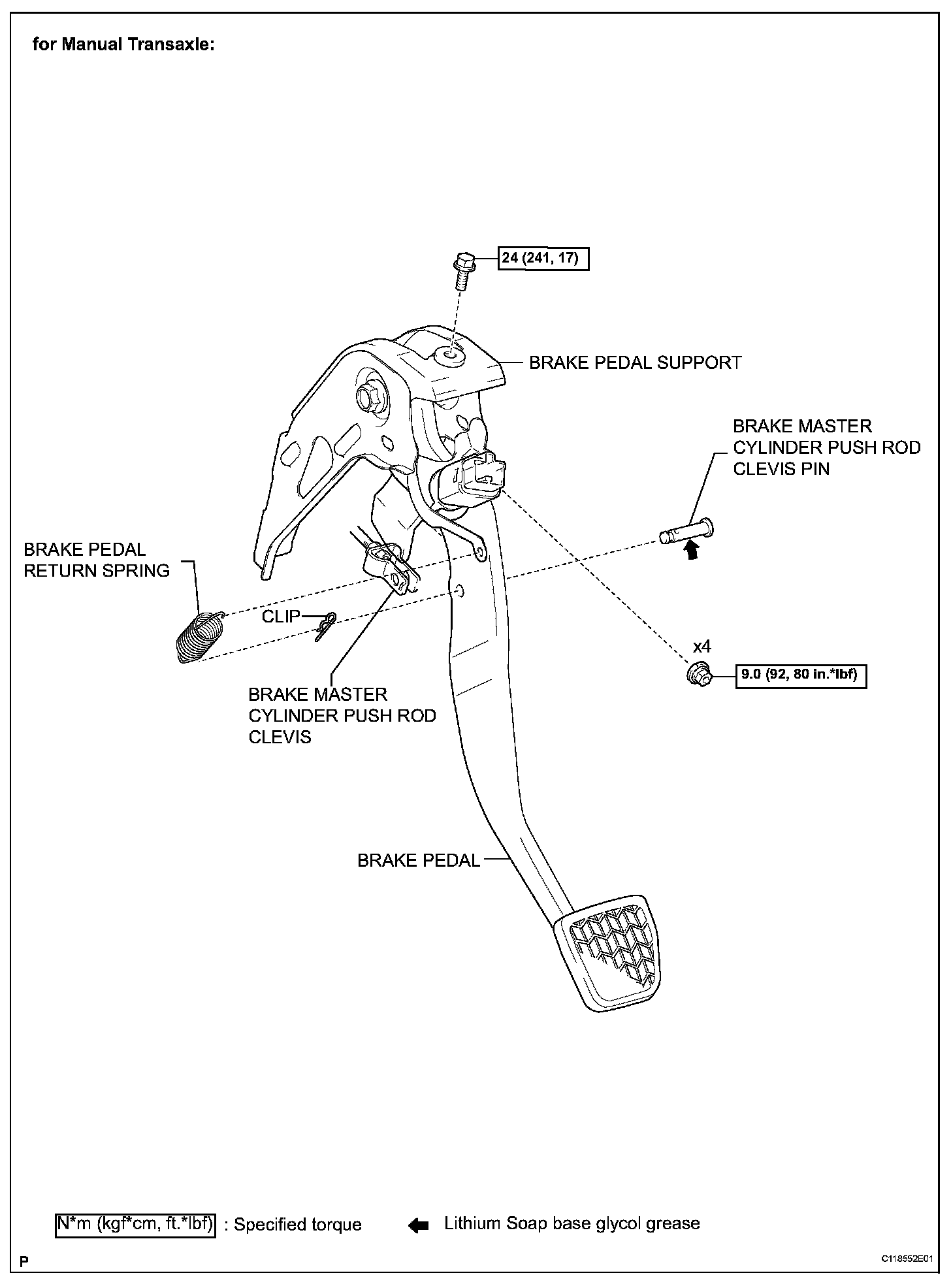
63. REMOVE BRAKE MASTER CYLINDER PUSH ROD CLEVIS (for Manual Transaxle)
64. REMOVE BRAKE PEDAL SUPPORT SUB-ASSEMBLY (for Manual Transaxle)
65. REMOVE STEERING COLUMN ASSEMBLY
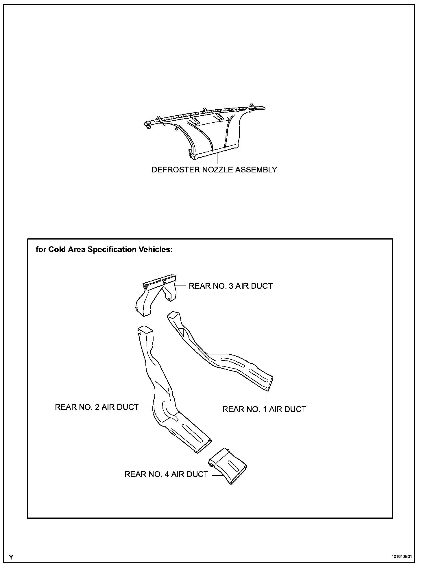
66. REMOVE DEFROSTER NOZZLE ASSEMBLY
a. Disconnect the connectors and clamps.
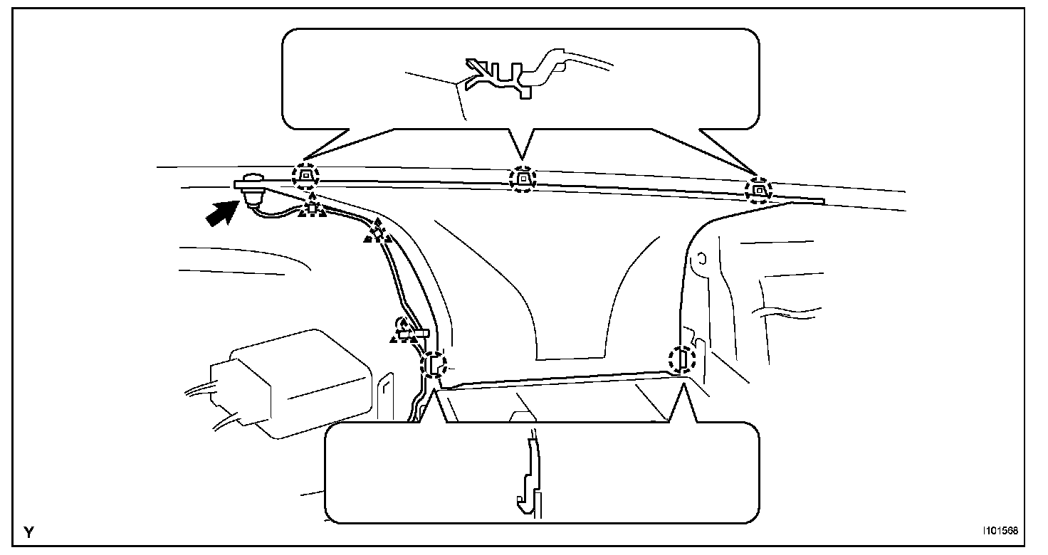
b. Disengage the 5 claws and remove the defroster nozzle.
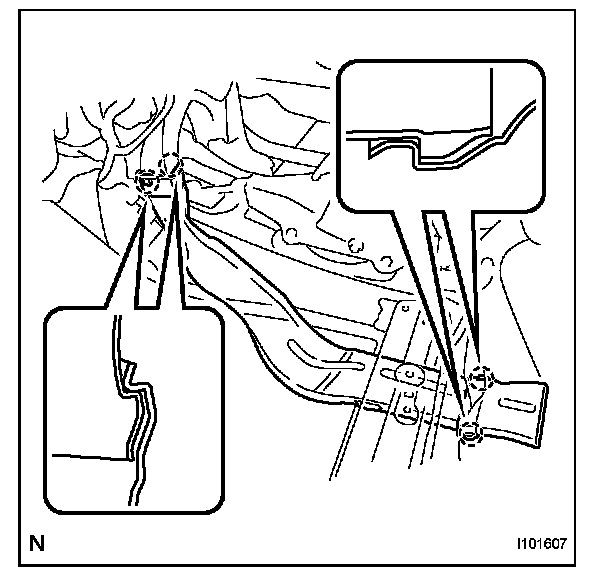
67. REMOVE REAR NO. 2 AIR DUCT (for Cold Area Specification Vehicles)
a. Disengage the 4 claws and remove the air duct.
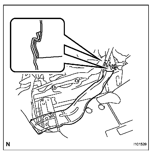
68. REMOVE REAR NO. 1 AIR DUCT (for Cold Area Specification Vehicles) a. Disengage the 2 claws and remove the air duct.
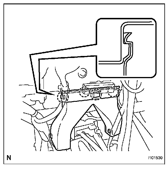
69. REMOVE REAR NO. 3 AIR DUCT(for Cold Area Specification Vehicles)
a. Disengage the 4 claws and remove the air duct.
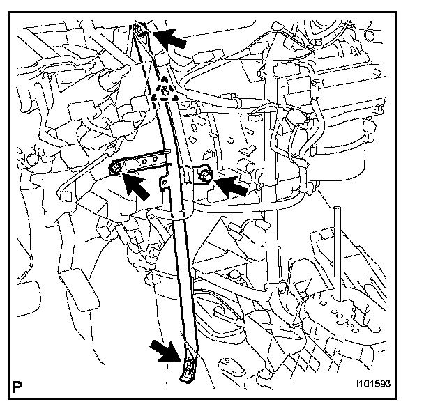
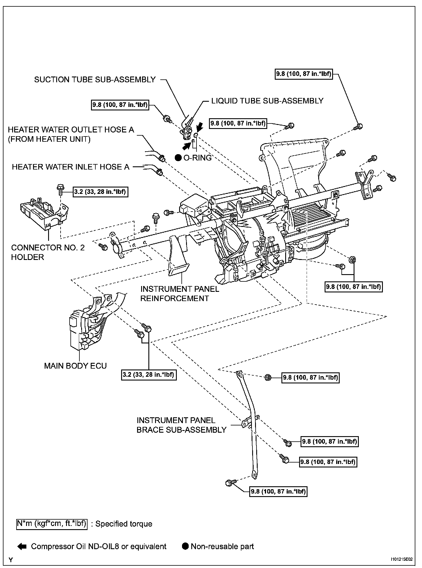
70. REMOVE INSTRUMENT PANEL BRACE SUB-ASSEMBLY
a. Disengage the clamp.
b. Remove 2 bolts, screw and nut and remove the instrument panel brace.
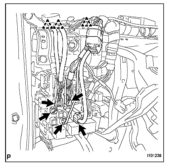
71. SEPARATE MAIN BODY ECU
a. Disconnect the 5 connectors and 3 clamps.
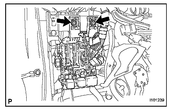
b. Remove the 2 bolts and separate the main body ECU.
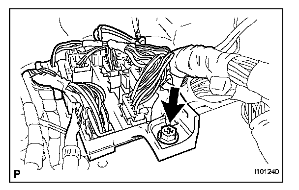
72. SEPARATE CONNECTOR NO. 2 HOLDER
a. Remove the bolt.
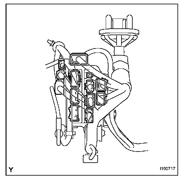
b. Disconnect the connectors and separate the connector NO. 2 holder.
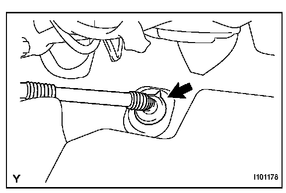
73. REMOVE INSTRUMENT PANEL REINFORCEMENT
a. Disconnect the drain hose.
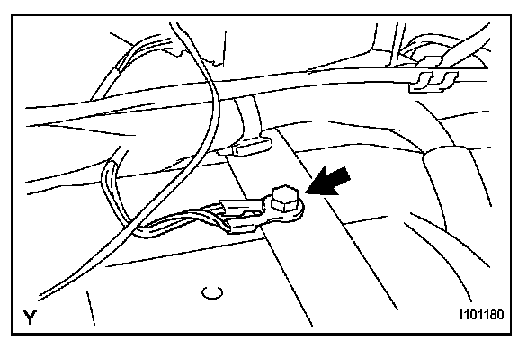
b. Remove the bolt and disconnect the ground wire.
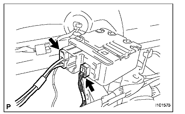
c. Disconnect the connector.
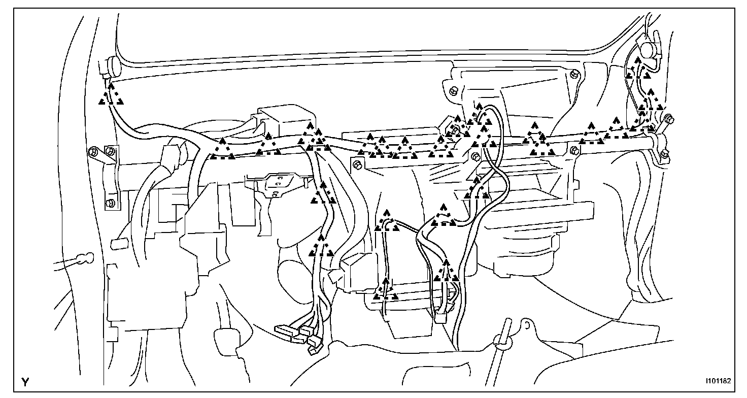
d. Disengage the clamps.
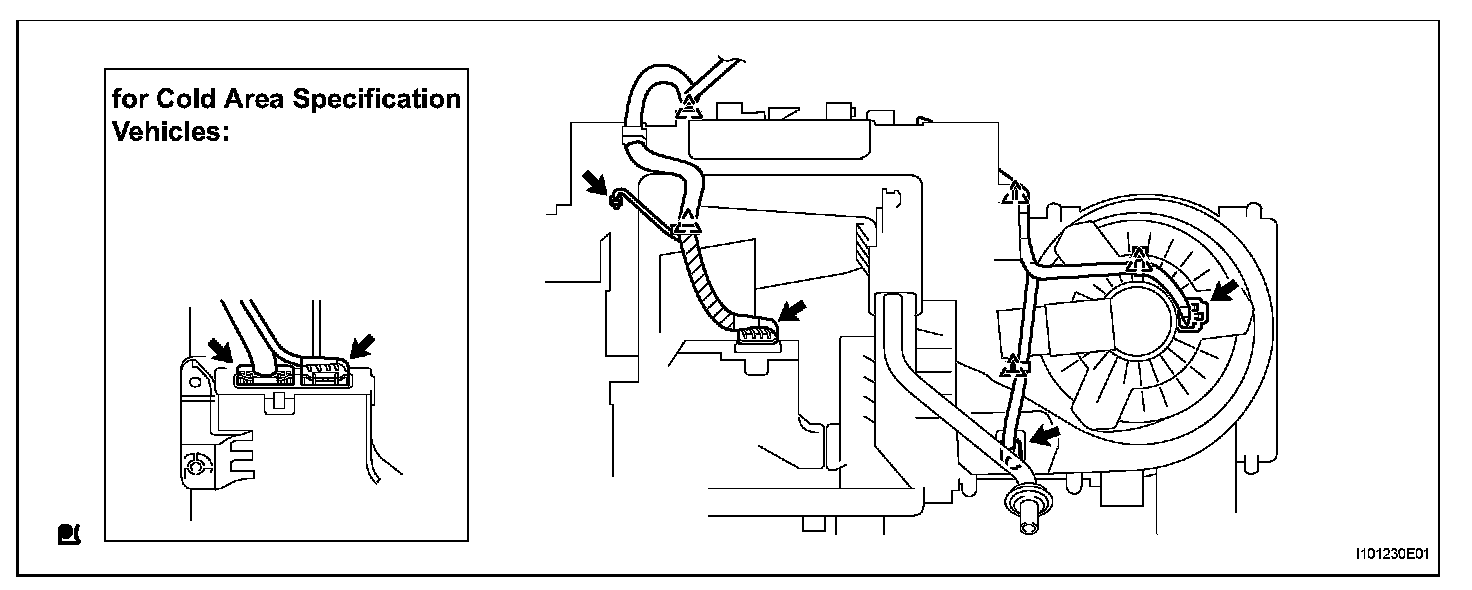
e Disconnect the connectors and clamps.
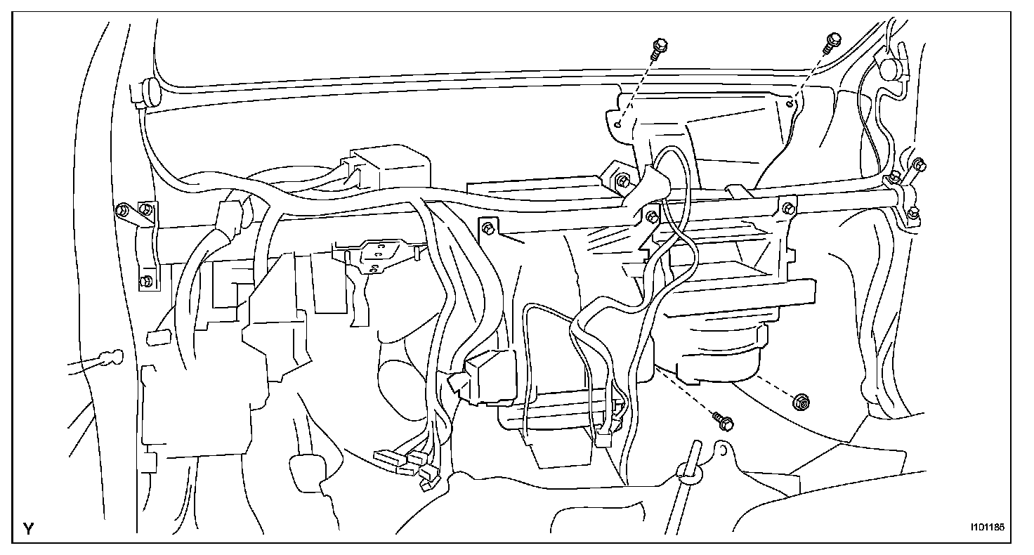
f. Remove the 3 bolts and the nut.
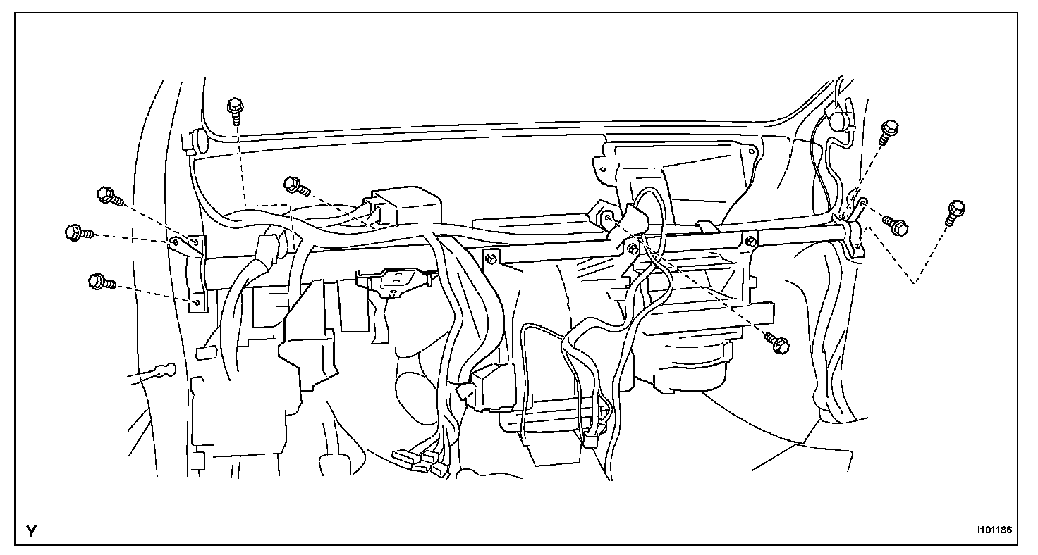
g. Remove the 9 bolts and remove the instrument panel reinforcement together with the air conditioning unit.
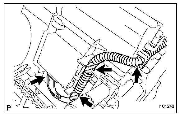
h. Disconnect the connector and the 3 clamps.
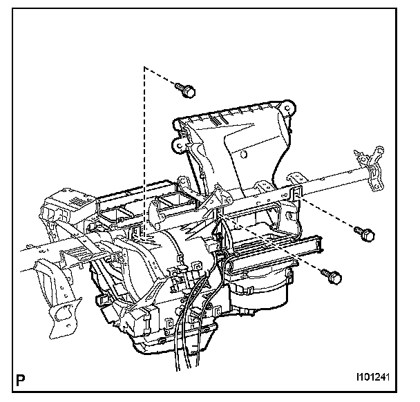
i. Remove the 3 screws and the air conditioning unit.
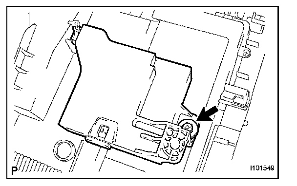
74. REMOVE AIR CONDITIONING AMPLIFIER ASSEMBLY
a. Remove the screw and the air conditioning amplifier.
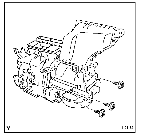
75. REMOVE AIR CONDITIONING UNIT
a. Remove the 3 screws and the air conditioning unit.
INSTALLATION
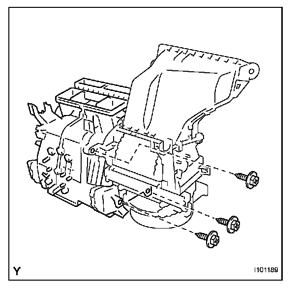
1. INSTALL AIR CONDITIONING UNIT
a. Install the air conditioning unit with the 3 screws.
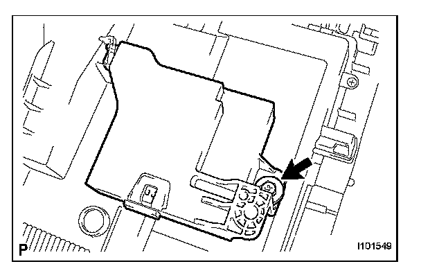
2. INSTALL AIR CONDITIONING AMPLIFIER ASSEMBLY
a. Install the air conditioning amplifier with the screw.
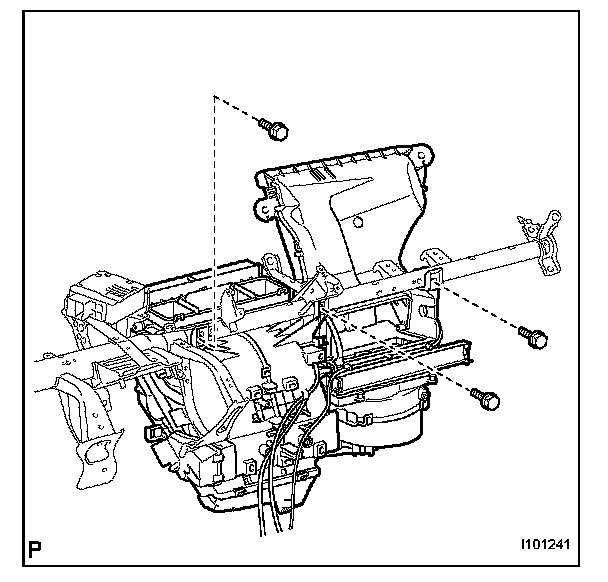
3. INSTALL INSTRUMENT PANEL REINFORCEMENT
a. Provisionally tighten the air conditioning unit with the 3 screws.
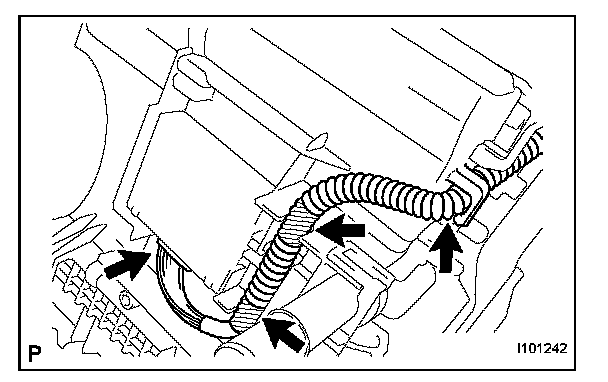
b. Connect the connector and the 3 clamps.
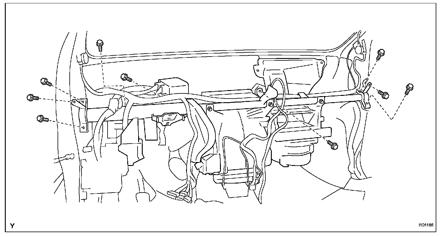
c. Install the instrument panel reinforcement and the air conditioning unit with the 9 bolts.
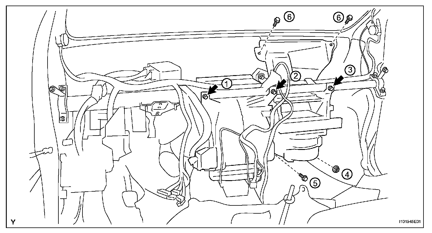
d. Install the 3 screws, 3 bolts and nut in the sequence shown in the illustration.
Torque:
4.0 N.m (41 kgf.cm, 35 in.lbf) for screw
9.8 N.m (100 kgf.cm,87 in.lbf) for nut
9.8 N.m (100 kgf.cm, 87 in.lbf) for bolt
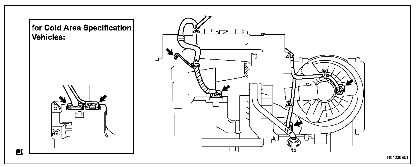
e. Install the wire harness with the clamps and connectors.
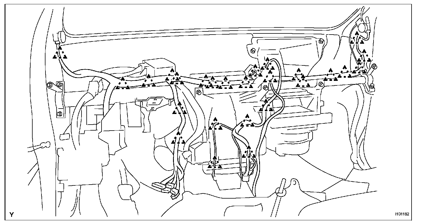
f. Engage the clamps.
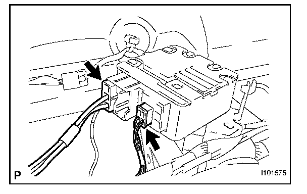
g. Connect the connectors.
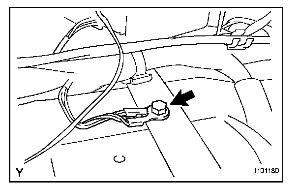
h. Install the ground wire with the bolt.
Torque: 3.2 N.m (33 kgf.cm, 28 in.lbf)
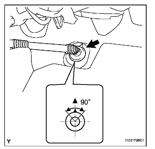
i. Install the drain hose into the position shown in the illustration.
NOTE:
- Install the drain hose with its UP mark facing upward, within the 90 degree range shown in the illustration.
- Install the drain hose without twisting it.
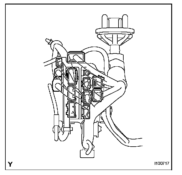
4. INSTALL CONNECTOR NO. 2 HOLDER
a. Connect the connectors and install the wire harness.
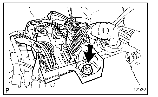
b. Install the connector holder with the bolt.
Torque: 3.2 N.m (33 kgf.cm, 28 in.lbf)
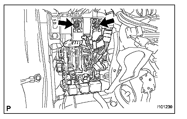
5. INSTALL MAIN BODY ECU
a. Install the main body ECU with the 2 bolts.
Torque: 3.2 N.m (33 kgf.cm, 28 in.lbf)
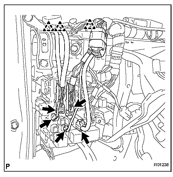
b. Connect the 5 connectors and the 3 clamps.
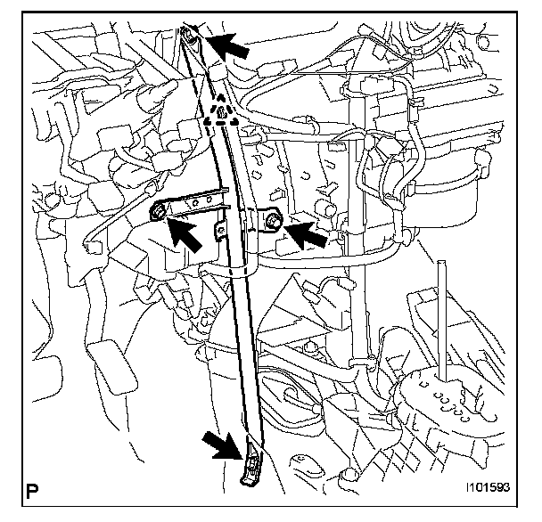
6. INSTALL INSTRUMENT PANEL BRACE SUB-ASSEMBLY
a. Install the instrument panel brace with the 2 bolts, screw and nut.
Torque:
9.8 N.m (100 kgf.cm, 87 in.lbf) for screw
9.8 N.m (100 kgf.cm, 87 in.lbf) for nut
9.8 N.m (100 kgf.cm, 87 in.lbf) for bolt
b. Engage the clamp.
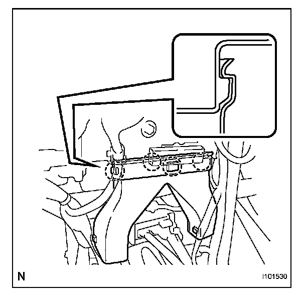
7. INSTALL REAR NO. 3 AIR DUCT (for Cold Area Specification Vehicles)
a. Engage the 4 claws and install the air duct.
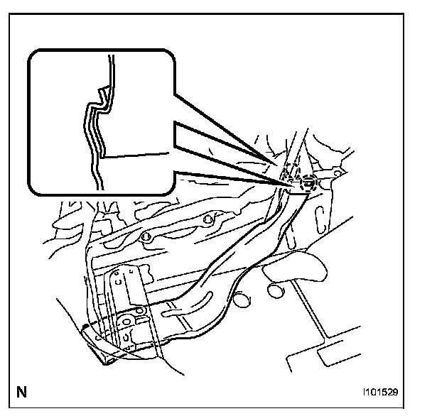
8. INSTALL REAR NO. 1 AIR DUCT (for Cold Area Specification Vehicles)
a. Engage the 2 claws and install the air duct.
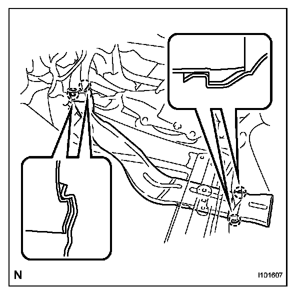
9. INSTALL REAR NO. 2 AIR DUCT (for Cold Area Specification Vehicles)
a. Engage the 4 claws and install the air duct.
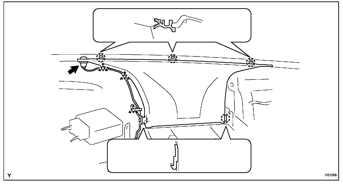
10. INSTALL DEFROSTER NOZZLE ASSEMBLY
a. Engage the 5 claws and install the defroster nozzle.
b. Connect the clamps and connectors and install the wire harness.
11. INSTALL STEERING COLUMN ASSEMBLY
12. INSTALL BRAKE PEDAL SUPPORT SUB-ASSEMBLY (for Manual Transaxle)
13. INSTALL BRAKE MASTER CYLINDER PUSH ROD CLEVIS (for Manual Transaxle)
14. INSTALL BRAKE PEDAL (for Automatic Transaxle)
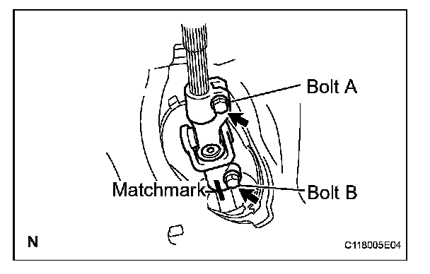
15. INSTALL STEERING SLIDING YOKE SUB-ASSEMBLY
a. Align the matchmarks and install the sliding yoke onto the power steering assembly with bolt B.
Torque: 28 N.m (286 kgf.cm, 21 ft.lbf)
b. Tighten bolt A.
Torque: 28 N.m (286 kgf.cm, 21 ft.lbf)
16. INSTALL COLUMN HOLE COVER SILENCER SHEET
17. INSTALL INSTRUMENT PANEL SUB REINFORCEMENT
18. CONNECT POWER STEERING ECU ASSEMBLY
19. INSTALL COMBINATION SWITCH ASSEMBLY
20. INSTALL STEERING COLUMN COVER
21. INSTALL STEERING WHEEL ASSEMBLY
22. INSTALL STEERING PAD
23. INSTALL LOWER INSTRUMENT PANEL SUB-ASSEMBLY
24. CONNECT HOOD LOCK CONTROL LEVER SUB-ASSEMBLY
25. CONNECT ANTENNA CORD SUB-ASSEMBLY
26. INSTALL NO. 6 HEATER TO REGISTER DUCT ASSEMBLY
27. INSTALL INSTRUMENT PANEL BOX
28. INSTALL INSTRUMENT PANEL FINISH PANEL SUB-ASSEMBLY LOWER
29. INSTALL CONSOLE BOX ASSEMBLY REAR
30. INSTALL CONSOLE BOX CARPET
31. INSTALL CONSOLE BOX REAR COVER
32. INSTALL SHIFTING HOLE COVER SUB-ASSEMBLY (for Manual Transaxle)
33. INSTALL SHIFT LEVER KNOB SUB-ASSEMBLY (for Manual Transaxle)
34. INSTALL COWL SIDE TRIM BOARD RH
35. INSTALL COWL SIDE TRIM BOARD LH
36. INSTALL INSTRUMENT PANEL UNDER COVER SUB-ASSEMBLY LH
37. INSTALL INSTRUMENT PANEL UNDER COVER SUB-ASSEMBLY RH
38. INSTALL FRONT DOOR SCUFF PLATE RH
39. INSTALL FRONT DOOR SCUFF PLATE LH
40. INSTALL UPPER INSTRUMENT PANEL SUB-ASSEMBLY
41. INSTALL GLOVE COMPARTMENT DOOR ASSEMBLY
42. INSTALL NO. 1 SWITCH HOLE BASE
43. INSTALL FRONT PILLAR GARNISH RH
44. INSTALL FRONT PILLAR GARNISH LH
45. INSTALL FRONT DOOR OPENING TRIM WEATHERSTRIP RH
46. INSTALL FRONT DOOR OPENING TRIM WEATHERSTRIP LH
47. CONNECT AIR INLET DAMPER CONTROL CABLE SUB-ASSEMBLY
48. CONNECT DEFROSTER DAMPER CONTROL CABLE SUB-ASSEMBLY
49. CONNECT AIR MIX DAMPER CONTROL CABLE SUB-ASSEMBLY
50. INSTALL AIR CONDITIONER PANEL SUB-ASSEMBLY
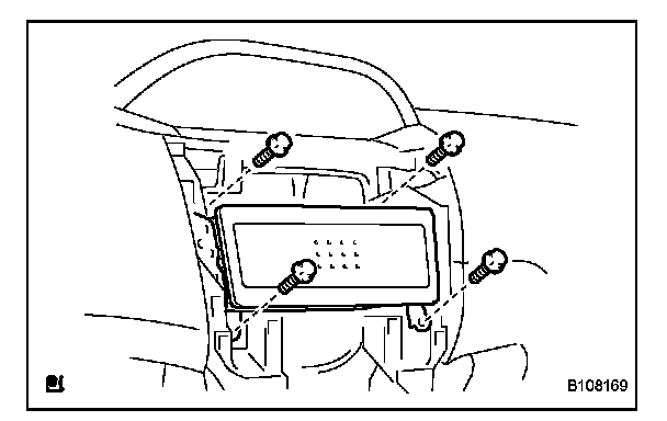
51. INSTALL RADIO TUNER OPENING COVER (w/o Radio Receiver)
a. Install the radio tuner opening cover with the 4 bolts.
52. INSTALL RADIO RECEIVER ASSEMBLY
53. INSTALL INSTRUMENT CLUSTER FINISH PANEL SUB-ASSEMBLY CENTER
54. INSTALL COMBINATION METER ASSEMBLY
55. INSTALL INSTRUMENT CLUSTER FINISH PANEL
56. INSTALL INSTRUMENT PANEL FINISH PANEL END RH
57. INSTALL INSTRUMENT PANEL FINISH PANEL END LH
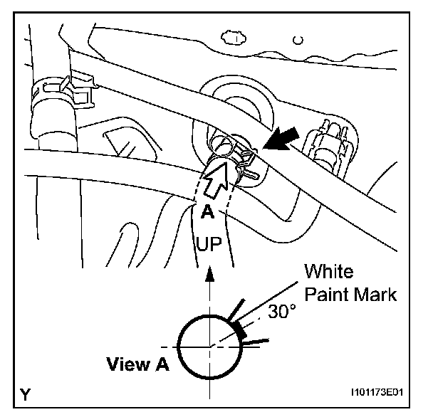
58. CONNECT HEATER WATER INLET HOSE A
a. Install the heater water inlet hose onto the heater unit.
NOTE: Perform the installation with the hose clip and mark at the correct angle.
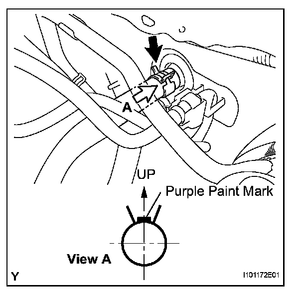
59. CONNECT HEATER WATER OUTLET HOSE A (FROM HEATER UNIT)
a. Install the heater water outlet hose onto the heater unit.
NOTE: Perform the installation with the hose clip and mark at the correct angle.
60. INSTALL LIQUID TUBE SUB-ASSEMBLY
a. Remove the vinyl tape from liquid tube and the connecting portion of the unit.
b. Apply sufficient compressor oil (ND-OIL8) to a new O-ring and the connecting part of liquid tube.
Compressor oil: ND-OIL8 or the equivalent
c. Install the O-ring onto liquid tube.
d. connect liquid tube to the unit.
61. INSTALL SUCTION TUBE SUB-ASSEMBLY
a. Remove the vinyl tape from the suction tube and the connecting part of the unit.
b. Apply sufficient compressor oil (ND-OIL8) to a new O-ring and the connecting part of suction tube.
Compressor oil: ND-OIL8 or the equivalent
c. Install the O-ring onto the suction tube.
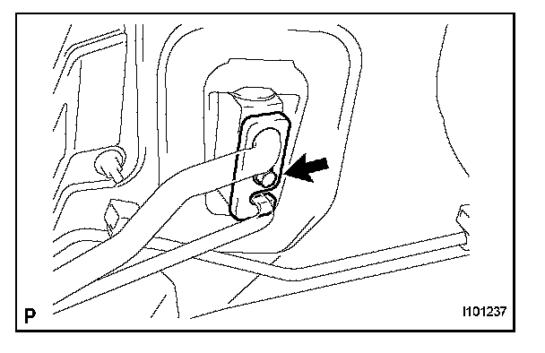
d. Move the hook connector in the direction indicated by the arrow in the illustration.
e. Insert the pipe joints securely into the fitting holes and tighten the bolt.
Torque: 9.8 N.m (100 kgf.cm, 87 in.lbf)
62. INSTALL COWL TOP PANEL OUTER
63. INSTALL NO. 2 COWL TO REGISTER DUCT SUB-ASSEMBLY
64. INSTALL FRONT WIPER MOTOR AND LINK
65. INSTALL COWL TOP VENTILATOR LOUVER LH
66. INSTALL COWL TOP VENTILATOR LOUVER SUB-ASSEMBLY
67. INSTALL HOOD TO COWL TOP SEAL
68. INSTALL FRONT WIPER ARM AND BLADE ASSEMBLY LH
69. INSTALL FRONT WIPER ARM AND BLADE ASSEMBLY RH
70. INSTALL FRONT WIPER ARM HEAD CAP
71. ADD ENGINE COOLANT
72. CONNECT CABLE TO NEGATIVE BATTERY TERMINAL
Torque: 5.4 N.m (55 kgf.cm)
73. CHECK SRS WARNING LIGHT
74. CHARGE REFRIGERANT
75. WARM UP ENGINE
76. CHECK FOR ENGINE COOLANT
77. CHECK FOR REFRIGERANT LEAK
78. POSITION FRONT WHEELS FACING STRAIGHT AHEAD