Installation
AIR CONDITIONING: AIR CONDITIONING UNIT: INSTALLATION
INSTALLATION
1. INSTALL AIR CONDITIONING UNIT ASSEMBLY
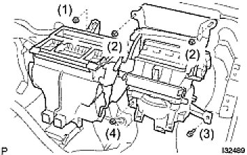
(a) Install the air conditioner unit assembly with the 4 nuts and bolt.
Torque: 9.8 Nm (100 kgf-cm, 87 in-lbf)
NOTE: Tighten the nuts and bolt in following order shown in the illustration to install the air conditioner unit assembly.
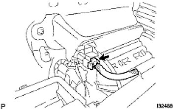
(b) Connect the connector to the cooler thermistor No. 1.

(c) Connect the connector to the damper servo sub-assembly.
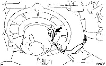
(d) Connect the connector to the blower with fan motor sub-assembly.
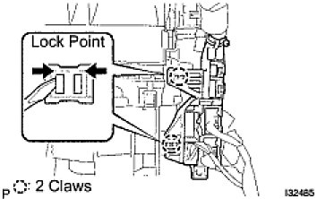
(e) Install the 2 fitting claws, connect the connector holder.
2. INSTALL ECM
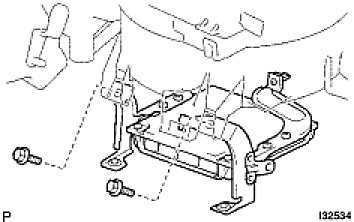
(a) Install the ECM with the 2 bolts.
Torque: 3.0 Nm (30 kgf-cm, 26 in-lbf)
- Do not apply excessive force to the connector of the ECM.
- Do not give any impact to the ECM.
3. INSTALL INSTRUMENT PANEL SUB-ASSEMBLY LOWER
4. INSTALL DEFROSTER DAMPER CONTROL CABLE SUB-ASSEMBLY
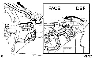
(a) Set the arm in FACE position.
(b) Install the inner cable end to the control lever with the arm in FACE position.
(c) Install the outer cable to the cable clamp while slightly pressing it in the direction of the arrow.
NOTICE:
- Be careful not to bend the cable wire.
- If the cable wire bends, the heater control assembly operationally becomes worse.
HINT: Operating the mode control lever, check that it properly stops at both ends of FACE and DEF and no recoil is identified.
5. INSTALL AIR MIX DAMPER CONTROL CABLE SUB-ASSEMBLY
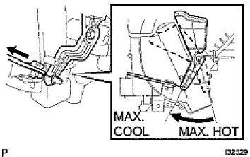
(a) Set the arm in MAX. COOL position.
(b) Install the inner cable end to the control lever with the arm in MAX. COOL position.
(c) Install the outer cable to the cable clamp while slightly pressing it in the direction of the arrow.
NOTICE:
- Be careful not to bend the cable wire.
- If the cable wire bends, the heater control assembly operationally becomes worse.
HINT: Operating the temperature control lever, check that it properly stops at both ends of MAX. COOL and MAX. HOT and no recoil is identified.
6. INSTALL HEATER CONTROL ASSEMBLY (Installation)
7. INSTALL INSTRUMENT PANEL SUB-ASSEMBLY UPPER (Installation)
8. INSTALL HEATER OUTLET WATER HOSE
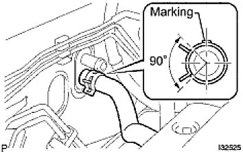
(a) Using pliers, grip the claws of clip and slide the clip and connect the heater outlet water hose.
- The clip is installing so that the projection of the clip may go into the 90° to a direction position.
- Marking of hose is installed upward by vehicle.
9. INSTALL HEATER INLET WATER HOSE
HINT: Connect in the same way as the heater outlet water hose.
10. INSTALL AIR CONDITIONING TUBE ASSEMBLY

(a) Lubricate a new O-ring with compressor oil and install them to the hose.
Compressor oil:
ND-OIL 8 or equivalent
(b) Install the air conditioning tube assembly and piping clamp.
HINT: After connection, check the fitting for claw of the piping clamp.
11. INSTALL SUCTION HOSE SUB-ASSEMBLY
(a) Lubricate a new O-ring with compressor oil and install them to the pipe.
Compressor oil:
ND-OIL 8 or equivalent
(b) Install the suction hose sub-assembly and piping clamp.
HINT: After connection, check the fitting for claw of the piping clamp.
12. ADD COOLANT
HINT:
- (Testing and Inspection) for 1ZZ-FE.
13. INSPECT FOR ENGINE COOLANT LEAK
HINT:
- (Testing and Inspection) for 1ZZ-FE.
14. CHARGE REFRIGERANT (Service and Repair)
15. WARM UP ENGINE
16. INSPECT LEAKAGE OF REFRIGERANT (Service and Repair)