Installation
FRONT SUSPENSION: FRONT SUSPENSION MEMBER: INSTALLATION
1. INSTALL FRONT STABILIZER BAR Installation
2. INSTALL FRONT SUSPENSION MEMBER FRONT BRACE LH Installation
3. INSTALL FRONT SUSPENSION MEMBER FRONT BRACE RH Installation
4. TEMPORARILY TIGHTEN FRONT NO. 1 LOWER SUSPENSION ARM SUB-ASSEMBLY LH
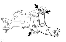
(a) Temporarily tighten the front No. 1 lower suspension arm sub-assembly LH to the front suspension crossmember with the 2 bolts and nut.
NOTICE:
Because the nut has its own stopper, do not turn the nut. Tighten the bolt with the nut secured.
5. TEMPORARILY TIGHTEN FRONT NO. 1 LOWER SUSPENSION ARM SUB-ASSEMBLY RH
HINT
Perform the same procedure as for the LH side.
6. INSTALL STEERING LINK ASSEMBLY Installation
7. INSTALL FRONT CROSS MEMBER SUB-ASSEMBLY
(a) Using a transmission jack, support the engine assembly with transaxle.
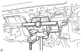
(b) Install the front cross member sub-assembly with the 4 bolts.
Torque : 96 Nm (979 kgf-cm, 71 ft-lbf)
(c) Connect the front engine mounting insulator with the 2 bolts.
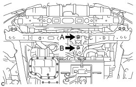
Torque : 95 Nm (969 kgf-cm, 70 ft-lbf)
NOTICE:
Temporarily tighten bolt B and then fully tighten the 2 bolts in the order of A and B.
8. INSTALL FRONT SUSPENSION CROSSMEMBER SUB-ASSEMBLY
(a) Support the front suspension crossmember sub-assembly with an engine lifter using 4 attachments or equivalent tools.
NOTICE:
* Make sure to secure the front suspension crossmember sub-assembly to prevent it from dropping.
* Use the attachments to keep the front suspension crossmember sub-assembly level.
* The front suspension crossmember sub-assembly is a heavy component. Make sure that it is supported securely.
(b) Tighten 2 new bolts on the left and right sides while alternately inserting SST into the left and right side reference holes in the front suspension crossmember sub-assembly.
SST : 09670-00020

Text in Illustration

Torque : 137 Nm (1397 kgf-cm, 101 ft-lbf)
(c) Lower the engine lifter.
(d) Install the rear engine mounting insulator with bolts A and B, and nuts C and D by tightening them in several steps.
Bolt A, B, Nut C, D - Torque : 95 Nm (969 kgf-cm, 70 ft-lbf)
NOTICE:
Temporarily tighten bolt A, and then fully tighten the 2 bolts and 2 nuts in the order of B, D, C, and A.
(e) Install the 2 wire harness clamp brackets with the 2 bolts.
Torque : 13 Nm (127 kgf-cm, 9 ft-lbf)
9. INSTALL FRONT SUSPENSION MEMBER REAR BRACE LH
(a) Install the front suspension member rear brace LH with 2 bolts B and new bolt A.
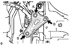
Bolt A - Torque : 137 Nm (1397 kgf-cm, 101 ft-lbf)
Bolt B - Torque : 93 Nm (948 kgf-cm, 69 ft-lbf)
(b) Install the clip.
10. INSTALL FRONT SUSPENSION MEMBER REAR BRACE RH
HINT
Perform the same procedure as for the LH side.
11. INSTALL REAR SIDE RAIL REINFORCEMENT SUB-ASSEMBLY LH
(a) Install the rear side rail reinforcement sub-assembly LH with the 4 bolts.
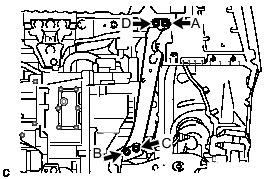
Torque : 96 Nm (979 kgf-cm, 71 ft-lbf)
NOTICE:
Temporarily tighten bolts A and B, and then fully tighten the 4 bolts in the order of C, B, D and A.
12. INSTALL REAR SIDE RAIL REINFORCEMENT SUB-ASSEMBLY RH
(a) Install the rear side rail reinforcement sub-assembly RH with the 4 bolts.
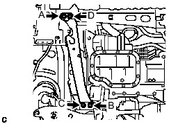
Torque : 96 Nm (979 kgf-cm, 71 ft-lbf)
NOTICE:
Temporarily tighten bolts A and B, and then fully tighten the 4 bolts in the order of C, B, D and A.
13. INSTALL FRONT ENGINE SUPPORT BRACKET REINFORCEMENT SUB-ASSEMBLY
(a) Install the front engine support bracket reinforcement sub-assembly with the 2 bolts.
Torque : 96 Nm (979 kgf-cm, 71 ft-lbf)
14. CONNECT FRONT NO. 1 LOWER SUSPENSION ARM SUB-ASSEMBLY LH Installation
15. CONNECT FRONT NO. 1 LOWER SUSPENSION ARM SUB-ASSEMBLY RH
HINT
Perform the same procedure as for the LH side.
16. CONNECT TIE ROD END SUB-ASSEMBLY LH Installation
17. CONNECT TIE ROD END SUB-ASSEMBLY RH
HINT
Perform the same procedure as for the LH side.
18. INSTALL FRONT STABILIZER LINK ASSEMBLY LH
(a) Install the front stabilizer link assembly LH to the front stabilizer bar with the nut.
Torque : 74 Nm (755 kgf-cm, 55 ft-lbf)
HINT
If the ball joint turns together with the nut, use a hexagon wrench (6 mm) to hold the stud bolt.
19. INSTALL FRONT STABILIZER LINK ASSEMBLY RH
HINT
Perform the same procedure as for the LH side.
20. CONNECT NO. 1 STEERING COLUMN HOLE COVER SUB-ASSEMBLY Installation
21. CONNECT NO. 2 STEERING INTERMEDIATE SHAFT ASSEMBLY Installation
22. INSTALL COLUMN HOLE COVER SILENCER SHEET Installation
23. INSTALL FRONT WHEELS
Torque : 103 Nm (1050 kgf-cm, 76 ft-lbf)
24. STABILIZE SUSPENSION
(a) Lower the vehicle.
(b) Press down on the vehicle several times to stabilize the suspension.
25. FULLY TIGHTEN FRONT NO. 1 LOWER SUSPENSION ARM SUB-ASSEMBLY LH Installation
26. FULLY TIGHTEN FRONT NO. 1 LOWER SUSPENSION ARM SUB-ASSEMBLY RH
HINT
Perform the same procedure as for the LH side.
27. INSTALL REAR ENGINE UNDER COVER LH
28. INSTALL REAR ENGINE UNDER COVER RH
29. INSTALL NO. 3 ENGINE UNDER COVER
30. INSTALL NO. 2 ENGINE UNDER COVER
31. INSTALL NO. 1 ENGINE UNDER COVER ASSEMBLY
32. INSTALL FRONT SPOILER COVER (w/ Front Spoiler)
33. INSPECT AND ADJUST FRONT WHEEL ALIGNMENT
Front Wheel Alignment