Plug-In Charge Control System
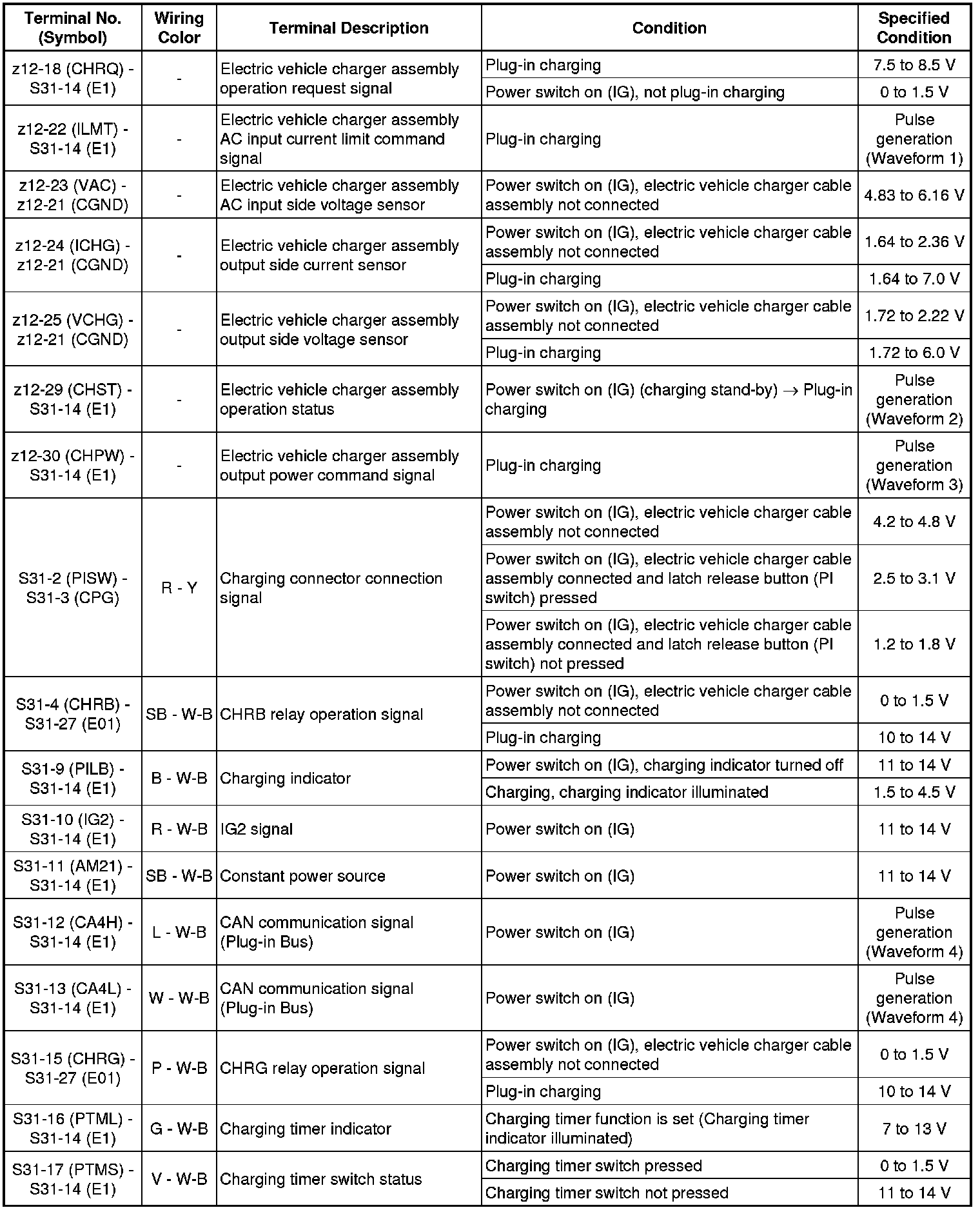
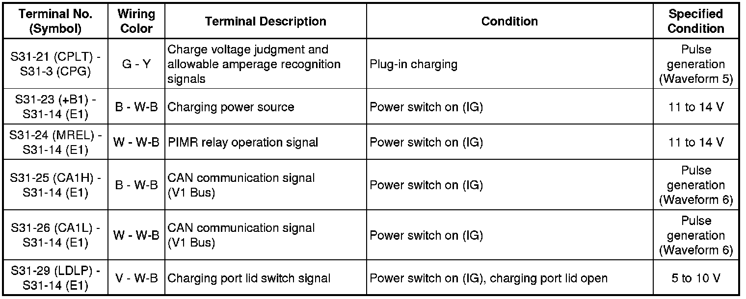
HYBRID / BATTERY CONTROL: PLUG-IN CHARGE CONTROL SYSTEM: TERMINALS OF ECU

Text in Illustration

Plug-in charge control ECU assembly
1. Oscilloscope waveforms
HINT
Oscilloscope waveform samples are provided here for informational purposes. Noise and fluttering waveforms have been omitted.
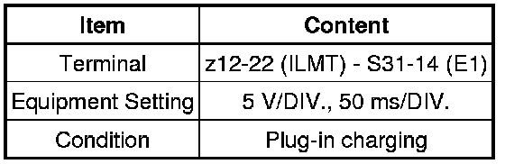
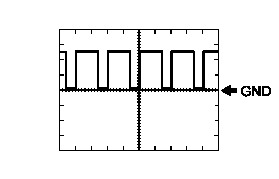
(a) Waveform 1 (Electric vehicle charger assembly AC input current limit command signal)
HINT
Duty ratio varies by the AC input current limit value of the electric vehicle charger assembly.
(b) Waveform 2 (Electric vehicle charger assembly operation status)

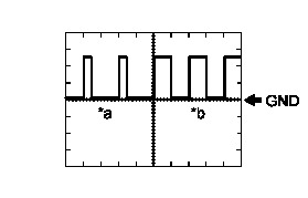
Text in Illustration

(c) Waveform 3 (Electric vehicle charger assembly output power command signal)
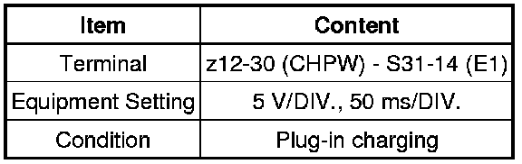
HINT
Duty ratio varies by the output power command value of the electric vehicle charger assembly.
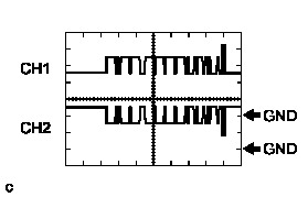
(d) Waveform 4 (CAN communication signal (Plug-in Bus))
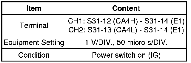
HINT
The waveform will vary depending on the content of the digital communication (digital signal).
(e) Waveform 5 (Charge voltage judgment and allowable amperage recognition signals)
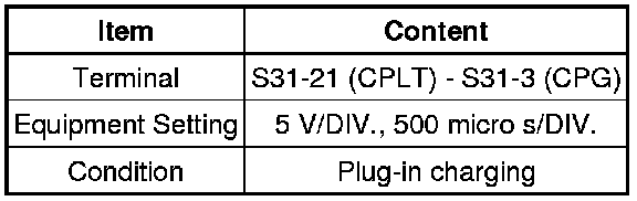
HINT
Duty ratio varies by the AC input allowable amperage of the charging cable and charging station.
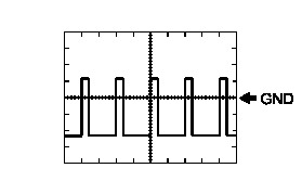
(f) Waveform 6 (CAN communication signal (V1 Bus))
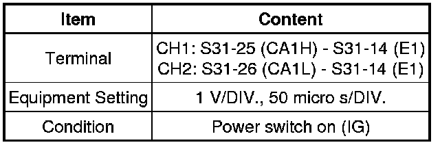
HINT
The waveform will vary depending on the content of the digital communication (digital signal).