Fuel Filter - Installing Water Indicator Kit
83VW01Appllies To RABBIT, PICKUP
DIESEL/TURBO DIESEL
Group
23
Subject:
Fuel Filter
Part Identifier 2034
Key Points
Installing water-indicator Kit
C
Number
83-06
August 4, 1983
Water level indicator light will light when it is necessary to drain water from trap in fuel filter
Parts required
Qty Description Part No...
1 water level indicator kit 175 998 030
1 "double" (single female into
double male) electrical connector local supply
1 6 mm "ring type" electrical
connector local supply
1 "Scotchlock" electrical connector local supply
2 8 mm "ring type" electrical
connectors (turbo only) local supply
Installation procedure
- disconnect battery ground cable
- remove left side underdash trim and closeout panels
- drop down Fuse/Relay Panel
Mount control unit as follows:
- mount retaining clip (included in Kit) to left side of steering column mounting bracket so control unit can be clipped in with connections pointing down
- install double connector on terminal 15 of control unit
- clip control unit in place
Install and connect water sensor as follows:
- replace water drain-screw in fuel filter with drain screw/sensor included in Kit
- connect blue wire (included in Kit) to terminal on new drain-screw/sensor and route it across firewall to where right hand engine harness enters interior
- route blue wire through firewall with engine harness, and connect to terminal A of control unit
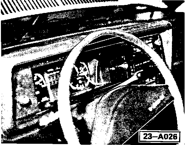
Install and connect indicator light as follows:
- remove instrument panel faceplate
- locate and drill a 9 mm hole directly to left of cold-start cable opening and centered between cold-start cable opening and instrument cluster cut-out
- mount indicator light (arrow) in face plate and connect both yellow and white wires (included in Kit) to light
- reinstall face plate and route wires through dash to control unit
- connect white wire from light to one male terminal of double connector on terminal 15 of control unit
- connect yellow wire to terminal 31b of control unit
- connect black wire (included in Kit) to remaining male terminal of double connector on terminal 15 of control unit
- route wire to black, 10 point, multi-point connector by Fuse/Relay Panel and splice black wire into green/blue wire leading to pin 3 with a "Scotchlock" connector
- connect brown wire (included in Kit) to terminal 31 of control unit and to harness-ground screw above Fuse/Relay Panel on right side
Note - Turbo only
Fuel filter has rubber mounts. To insure adequate grounding of filter on these models, a ground wire should be made and installed to bridge rubber mounts on filter
- reinstall Fuse/Relay Panel
- reinstall left side underdash trim and closeout panels
- reconnect battery
- test system by switching ignition on and grounding blue wire from sensor on fuel filter casing. Light should come on and remain on until ignition is switched off
Suggested Installation Time: 75 T.U.
Labor Operation: 20 34 31 0