Timing Chain Overviews
Timing Chain Overviews
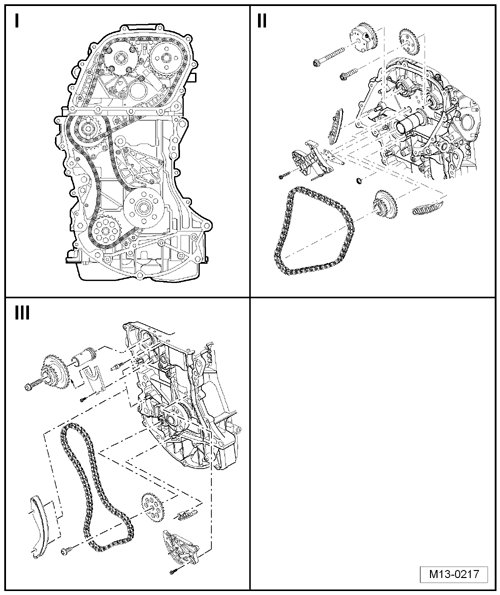
I - => [ Routing Overview ]
II - => [ Timing Chain, Camshafts ]
III - => [ Timing Chain, Oil Pump ]
Routing Overview
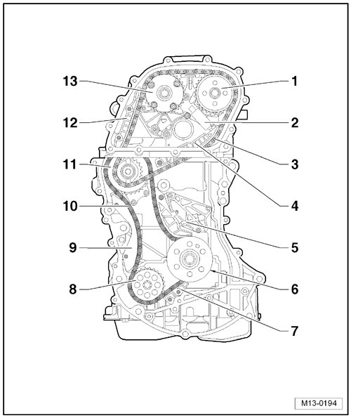
1 Sprocket, for the Exhaust Camshaft
2 Chain Tensioner, for the Camshaft Timing Chain
• At the top, with a sliding insert.
3 Timing Chain, for the Camshafts
4 Tensioning Rail, for the Camshaft Timing Chain
• For the chain tensioner.
• Secured to the cylinder block.
5 Chain Tensioner, for the Oil Pump Timing Chain
• With a tensioning rail.
6 Sprocket, for the Crankshaft
• Component of the crankshaft.
7 Guide Rail, for the Oil Pump Timing Chain
• Secured to the upper oil pan.
8 Sprocket, for the Oil Pump
• Removing and installing, refer to one of the following
• Engine codes BGP and BGQ, refer to => [ Oil Pump ] Oil Pump.
• Engine codes CBTA and CBUA, refer to => [ Oil Pump ] Oil Pump.
9 Guide Rail, for the Oil Pump Timing Chain
10 Timing Chain, for the Oil Pump
• From MY 08 the roller chain has been changed to a toothed chain.
11 Double Sprocket, for the Camshaft and Oil Pump Timing Chains
12 Glide Rail, for the Camshaft Timing Chain
13 Camshaft Adjuster, for the Intake Camshaft
• With the sprocket.
Timing Chain, Camshafts
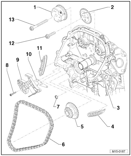
1 Camshaft Adjuster, for the Intake Camshaft
• With a sprocket.
• Do not disassemble.
2 Sprocket, for the Exhaust Camshaft
• Not pressed on the camshaft.
• When removing, press off lightly if necessary.
3 Cylinder Head
4 Tensioning Rail
• For chain tensioner.
• Secured to the cylinder block.
• Lubricate before installing the pin.
5 Double Sprocket
• Securing, refer to => [ Timing Chain, Oil Pump ].
6 Timing Chain
• Removing:
- The procedure is the same as for "Valve Timing, Adjusting". Refer to => [ Valve Timing, Adjusting ] Adjustments.
- Remove the vacuum pump. Refer to => [ Brake Booster Vacuum Pump ] Brake Booster Vacuum Pump.
- Mark the direction of travel.
• Note when installing:
- Install in the original direction of rotation.
- The chain must lie correctly in the tensioning and guide rails.
- Adjust the valve timing. Refer to => [ Valve Timing, Adjusting ] Adjustments.
7 Strainer
• Always replace.
8 Bolt
• 10 Nm
9 Chain Tensioner
• Secure using the locking pins (T03006).
10 Gasket
• Always replace.
11 Guide Rail
• Lubricate before installing the pin.
12 Bolt
• 60 Nm + 90° (1/4) additional turn.
• Always replace.
13 Bolt
• 60 Nm + 90° (1/4) additional turn.
• Always replace.
Timing Chain, Oil Pump
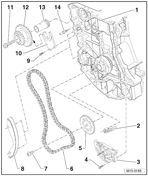
1 Cylinder Block
2 Guide Rail
• Secured to the upper oil pan.
• Lubricate before installing the pin.
3 Chain Tensioner
• Secure using the locking pins (T10115).
4 Bolt
• 10 Nm
5 Sprocket, for the Oil Pump
• Removing and installing, refer to one of the following:
• Engine code BGP and BGQ, refer to => [ Oil Pump ] Oil Pump.
• Engine codes CBTA and CBUA, refer to => [ Oil Pump ] Oil Pump.
6 Timing Chain, for the Oil Pump
• From MY 08 the roller chain has been changed to a toothed chain.
• Removing:
- Remove the engine.
- Remove the control housing cover.
- Remove the timing chain.
- Remove the chain tensioner => [ (Item 3) Chain Tensioner ].
- Mark the direction of travel.
• Note when installing:
- Install in the original direction of rotation.
- The chain must lie correctly in the tensioning and guide rails.
- Adjust the valve timing. Refer to => [ Valve Timing, Adjusting ] Adjustments.
7 Bolt
• 20 Nm + 90° (1/4) additional turn.
• Always replace
8 Guide Rail
• Lubricate before installing the pin.
9 Bolt
• 10 Nm
10 Mount
• Engages in the groove in the sprocket => [ (Item 12) Double Sprocket ].
11 Bolt
• 60 Nm + 90° (1/4) additional turn.
• Always replace.
12 Double Sprocket
• Lubricate the journal before installing.
• Lubricate the groove for the mount => [ (Item 10) Mount ].
13 Gear Shaft
14 Threaded Pin
• 40 Nm
• For the chain tensioner for the oil pump timing chain.