Transmission Position Sensor/Switch: Service and Repair
Multifunction Transmission Range Switch (F125)
Special tools, testers and auxiliary items required
• Torque Wrench (5-50 Nm) (V.A.G 1331)
• Setting Gauge (T10173)
Removing
- Move the selector lever into the "N" position.
- Turn off the ignition.
- Disconnect the cable - arrows 1 - and then remove it from the cable bracket - arrow 2 -.
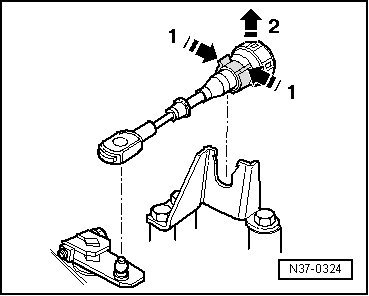
• Do not use pliers because the tabs on the cable bracket could break off.
• Do not bend the selector lever cable.
- Pry the cable - 1 - off the lever - 3 - using a open end wrench - 2 -.
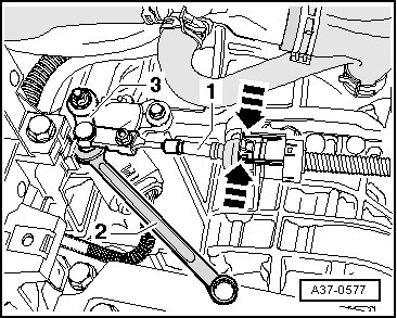
- Disconnect the connector from the multifunction transmission range switch.
- Remove the nut - 1 -.
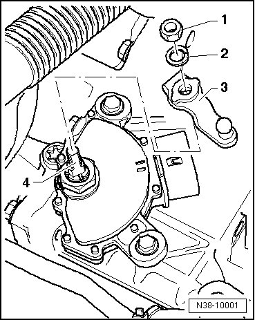
- Remove the spring washer - 2 - and the lever - 3 - from the selector shaft - 4 -.
- Bend back the hooks on the lock washer - 2 - using a screwdriver.
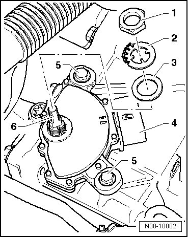
- Replace the lock washer is a hook breaks off.
- Remove the nut - 1 -.
- Remove the bolts - 5 -.
- Remove the multifunction switch - 4 - and the washers - 2 and 3 - from the selector shaft - 6 -.
Installing
Install in reverse order of removal.
- Attach the lever - 4 - to the selector shaft - 6 -.
- Install the bolts - 5 - for the multifunction switch hand tight.
- Bend back the hooks on the lock washer - 2 -.
- Install the washers - 2 and 3 - on the selector shaft - 6 -.
- Install the washer - 2 - with the hooks facing up.
- Install the washer - 2 - with the long narrow guide into the long narrow depressions in the selector shaft - 6 -.
- Tighten the nut - 1 - to 7 Nm.
- Tighten the nut - 1 - and secure it by bending the hook on the washer - 2 - upward.
- Replace the lock washer is a hook breaks off.
- Attach the lever - 3 - to the selector shaft - 4 -.
- Move the selector lever - 3 - into the "P" position. This means, push the selector lever - 3 - opposite the drive direction until it stops.
- Move the lever - 3 - into the "N" position. Push the lever - 3 - two position forward in the direction of travel.
- Mount the spring washer - 2 - and the nut - 1 - on the selector shaft - 4 -.
- Tighten the nut - 1 - to 13 Nm.
- Selector mechanism, checking. Refer to => [ Selector Mechanism through 02.2009, Checking ] Testing and Inspection.
Adjusting
- Move the selector lever into the "N" position.
- Do not bend the selector lever cable.
Adjustment Prerequisites
• Selector lever cable is disconnected at the selector shaft lever
• The selector shaft is in the "N" position.
• The bolts on the multifunction switch have been loosened.
• The lever/selector shaft is removed.
Perform the following procedure:
- Install the (T10173) on the selector shaft - 2 - and turn the multifunction switch - 1 - just until the (T10173) locks onto the tab on the connector on the multifunction switch.
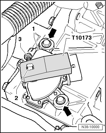
- Use the bolt - 3 - to secure the (T10173) to the selector shaft - 2 -.
- Tighten the bolts - arrows - to 6 Nm.
- Remove the (T10173).
- Further installation is performed in the reverse sequence, refer to.