EVAP System Component Overview
EVAP System Component Overview
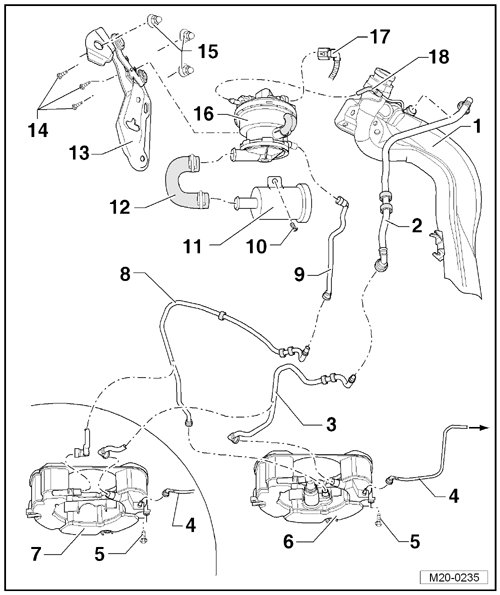
1 Fuel Tank
2 Vent Line
• Behind the right rear wheel housing liner.
3 Vent Line
• On the vehicle floor.
4 Vent Line
• To the EVAP canister purge regulator valve 1 (N80) at the intake manifold.
• To remove, press the release button.
5 Bolt
• 8 Nm
6 Evaporative Emission (EVAP) Canister
• for engine codes BGQ and CBUA.
• Installed location: On the bottom of the spare tire wheel well.
• Removing and installing, refer to => [ EVAP Canister ] Service and Repair.
7 EVAP Canister
• For engine codes BGP and CBTA.
• Installed location: On the bottom of the spare tire wheel well.
• Removing and installing, refer to => [ EVAP Canister ] Service and Repair.
8 Connecting Pipe
• Pressure side.
• On the vehicle floor.
9 Connecting Pipe
• Pressure side
• Behind the right rear wheel housing liner.
10 Bolt
• 3 Nm
11 Air Filter Housing
• For the leak detection pump.
12 Connecting Hose
• Intake side.
13 Bracket
• For the leak detection pump.
• Secured inside the right rear wheel housing.
14 Bolt
• 2 Nm
15 Nut
• 9 Nm
16 Leak Detection Pump (V144)
• Installed location: Under the right rear wheel housing liner.
• Removing and installing, refer to => [ ] Service and Repair.
17 Connector
• Black, 3-pin
18 Vacuum Line
• Vehicles through MY 09: from the intake manifold.
• Vehicles from MY 10: from the connection to the vacuum line between the vacuum pump and the brake booster.