Subframe, Stabilizer Bar and Control Arm Assembly Overview
Subframe, Stabilizer Bar and Control Arm Assembly Overview
• Welding and straightening work on supporting or wheel carrying components of the suspension is not permitted.
• Always replace self-locking nuts.
• Always replace corroded bolts/nuts.
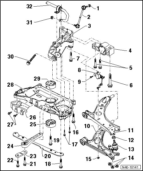
1 Nut, 65 Nm
• When tightening, counterhold on hex socket head of joint bolt.
• Self-locking
• Always replace after removal.
2 Coupling Rod
• Linking stabilizer to suspension strut.
3 Bracket
• Securing, refer to => [ Subframe, Securing ] Subframe, Securing.
• If bracket is replaced, vehicle must be aligned. Refer to => [ Wheel Alignment ] Wheel Alignment.
4 Mounting Bracket
• Securing, refer to => [ Subframe, Securing ] Subframe, Securing.
• With bonded rubber bushing.
5 Bolt, 50 Nm + 90°
• Always replace after removal.
6 Bolt, 70 Nm + 90°
• M12 x 1.5 x 90
• Always replace after removal.
7 Bolt, 70 Nm + 90°
• M12 x 1.5 x 90
• Always replace after removal.
8 Left Front Level Control System Sensor (G78)
• Can be tested in Guided Fault Finding using the Vehicle diagnosis, testing and information system (VAS 5051B)
9 Bolt, 9 Nm
10 Control Arm
• It is possible there are different control arm versions (steel, aluminum).
• Do not install control arms made of different versions or made of different materials on the right and left sides.
• Replace with ball joint if damaged.
• Removal and installation, refer to => [ Control Arm with Mounting Bracket ] Control Arm with Mounting Bracket.
• Bushing, replacing, refer to => [ Control Arm Bonded Rubber Bushing ] Service and Repair.
11 Control Arm
• It is possible there are different control arm versions (welded sheet steel, single sheet steel).
• Do not install control arms made of different versions or made of different materials on the right and left sides.
• Replace with ball joint if damaged.
• Removal and installation, refer to => [ Control Arm with Mounting Bracket ] Control Arm with Mounting Bracket.
• Bushing, replacing, refer to => [ Control Arm Bonded Rubber Bushing ] Service and Repair.
12 Nut, 60 Nm
• M12 x 1.5
• Self-locking
• Always replace after removal.
13 Ball Joint
• Checking, refer to => [ Ball Joint, Checking ] Procedures.
• Removal and installation, refer to => [ Ball Joint ] Removal and Replacement.
• Replace with control arm if damaged.
14 Nut
• Steel control arm: 60 Nm.
• Steel and aluminum control arms: 100 Nm.
• Self-locking
• Always replace after removal.
15 Nut, 9 Nm
16 Bolt, 70 Nm + 90°
• M12 x 1.5 x 100
• Always replace after removal.
17 Bolt, 20 Nm + 90°
• Always replace after removal.
18 Bolt, 70 Nm + 90°
• M12 x 1.5 x 75
• Always replace after removal.
19 Bolt, 100 Nm + 90°
• M14 x 1.5 x 70
• Only tighten when pendulum support is bolted to transmission.
• Always replace after removal.
20 Underbody Protection Bracket
21 Bolt
Always pay attention the bolt size and strength class. There are different tightening specifications.
• M10 x 75 strength class 8.8: 40 Nm + 90° turn
• M10 x 75 strength class 10.9: 50 Nm + 90° turn
From MY 2008, Heli-Coil inserts are installed in the threads for the pendulum support threaded connection in the 02Q manual transmissions.
On these and all other transmissions, use strength class 10.9 bolts.
If, in the 02Q manual transmissions, there is not Heli-Coil insert, then use 8.8 strength class bolts and the appropriate tightening specification.
• Always replace after removal
22 Bolt
Pay attention to the bolt strength class. There are different tightening specifications.
• M10 x 35 strength class 8.8: 40 Nm + 90° turn
• M10 x 35 strength class 10.9: 50 Nm + 90° turn
From MY 2008, Heli-Coil inserts are installed in the threads for the pendulum support threaded connection in the 02Q manual transmissions.
On these and all other transmissions, use strength class 10.9 bolts.
If, in the 02Q manual transmissions, there is not Heli-Coil insert, then use 8.8 strength class bolts and the appropriate tightening specification.
• Always replace after removal.
23 Bracket on Pendulum Support
• No replacement part.
24 Pendulum Support
• Bolt first to transmission, then to subframe.
• Various versions
25 Lower Bonded Rubber Bushing for Pendulum Support
• Servicing, refer to => [ Subframe Bushings ] Service and Repair.
26 Shield
27 Bolt, 6 Nm
• Self-tapping
28 Subframe
• Various versions
• Removal and installation, without steering gear, refer to => [ Subframe without Steering Gear ] Subframe without Steering Gear.
• Removal and installation, with steering gear, refer to => [ Subframe with Steering Gear ] Subframe with Steering Gear.
29 Upper Bonded Rubber Bushing for Pendulum Support
• Servicing, refer to => [ Subframe Bushings ] Service and Repair.
30 Bolt, 70 Nm + 180°
• M12 x 1.5 x 110
• Always replace after removal.
• Tighten only in curb weight position. Refer to => [ Wheel Bearing, Lifting to Curb Weight Position ] Front Suspension.
31 Nut, 65 Nm
• When tightening, counterhold on hex socket head of joint bolt.
• Self-locking
• Always replace after removal.
32 Stabilizer
• Various versions
• Removal and installation, refer to => [ Stabilizer Bar ] Stabilizer Bar.