Transfer Fuel Pump, Checking
Transfer Fuel Pump, Checking
Special tools, testers and auxiliary items required
• Hand held remote control (jumper).
• Multimeter.
• Electrical connector test lead set.
Test requirements
• Battery voltage at least 12.5 volts.
• Fuse (SC27) OK.
• Fuse (SC1) OK.
• Fuel Pump (FP) Control Module (J538) OK.
Checking voltage supply
- Remove the rear seat bench
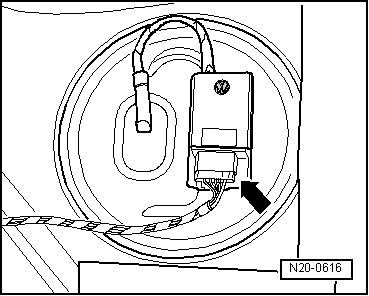
- Disconnect the Fuel Pump (FP) Control Module (J538) electrical harness connector - arrow -.
- Using a Multimeter, check the Fuel Pump (FP) Control Module (J538) electrical harness connector terminals 1 to 6 for voltage.
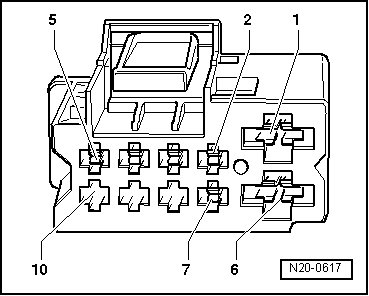
Specified value: battery (+).
If the specified value was not obtained:
- Check the wiring for a short circuit to Battery positive (+) or an open circuit.
- Check the electrical harness connector for damage, corrosion, lose or broken terminals.
- If necessary, repair the electrical circuit.
If the specified value was obtained:
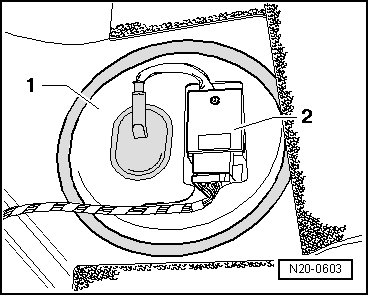
- Remove the cover - 1 - with the Fuel Pump (FP) Control Module (J538) - 2 - attached, from the fuel pump.
- Disconnect the fuel pump electrical harness connector from the fuel pump.
- Connect a Hand held remote control (jumper) to terminal - 1 - of the fuel pump electrical harness connector and to the vehicle battery (+).
- Connect a jumper cable from a Electrical connector test lead set to terminal - 5 - of the fuel delivery unit and to vehicle Ground (GND).
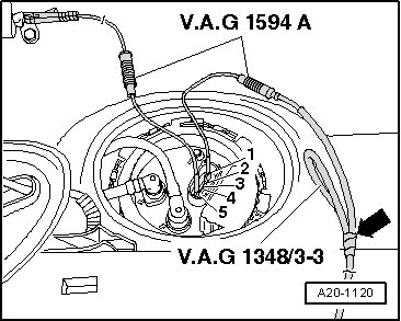
- Press switch on the Hand held remote control (jumper).
• The Fuel Pump (FP) runs quietly. Avoid surrounding noises while testing the fuel pump.
- Listen for an operating noise from the fuel pump.
If no operating noise is heard:
- Remove the fuel delivery unit.
- Using a Multimeter, check the electrical circuit between terminals - 1 - and - 5 - of the fuel delivery unit and the fuel pump for continuity.
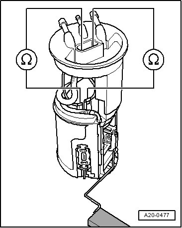
Specified value: 0 ohms.
If a malfunction is detected in the electrical circuit:
- Check the wiring for a short circuit to Battery positive (+) or an open circuit.
- Check the electrical harness connector for damage, corrosion, lose or broken terminals.
- If necessary, repair the electrical circuit.
- If no malfunction is detected in electrical circuit, replace the fuel pump.
Final procedures
After the repair work, the following work steps must be performed in the following sequence:
1. Check the DTC memory. Refer to => [ Diagnostic Mode 03 - Read DTC Memory ] Diagnostic Mode 03 - Read DTC Memory.
2. If necessary, erase the DTC memory. Refer to => [ Diagnostic Mode 04 - Erase DTC Memory ] Diagnostic Mode 04 - Erase DTC Memory.
3. If the DTC memory was erased, generate readiness code. Refer to => [ Readiness Code ] Readiness Code.