Steering Column Switch Base Plate
Steering Column Switch Base Plate
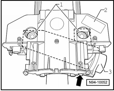
• To remove the steering column switch base carrier - 2 -, drill out the steering lock housing shear bolts. New shear bolts - 1 - are required for the subsequent installation.
• Before drilling out shear bolts, always make sure that components secured to base carrier are removed beforehand.
• By drilling out, drill shavings can reach the neighboring components, which can lead to damage and / or malfunctions!
• Follow the specified sequence when removing the components.
• When disconnecting and connecting the Battery, the procedure must be followed as described in the repair information. Refer to=> [ Battery, Disconnecting and Connecting ] Battery, Disconnecting and Connecting.
Removal
- Disconnect the battery. Refer to => [ Battery, Disconnecting and Connecting ] Battery, Disconnecting and Connecting.
Remove the following components in the correct order:
- Remove the steering wheel.
- Remove the steering column trim.
- Remove the steering column electronic systems control module (J527). Refer to=> [ Steering Column Electronic Systems Control Module ] Steering Column Electronic Systems Control Module (J527).
- Remove the airbag spiral spring/return spring with slip ring (F138). Refer to => [ Airbag Spiral Spring/Return Spring With Slip Ring ] Airbag Spiral Spring/Return Spring With Slip Ring (F138).
- Remove the steering angle sensor (G85). Refer to => [ Steering Angle Sensor ] Steering Angle Sensor (G85).
- Remove the turn signal switch (E2). Refer to => [ Turn Signal Switch ] Turn Signal Switch.
- Remove the windshield wiper switch (E). Refer to => [ Windshield Wiper Switch ] Windshield Wiper Switch (E).
- Disconnect the connector - arrow - from the anti-theft immobilizer reader coil (D2) - 3 -.
After components secured to base carrier have been removed, the base carrier can be removed:
- Drill out the bolts - 1 - on the steering lock housing - 3 -.
• Bolts M8 - 1 -, core hole diameter 6.8 mm.
- Remove the steering lock housing and the steering column switch base carrier - 2 - from the steering column to the rear.
- Remove the steering lock housing from the steering column switch base carrier.
Installation
Installation is performed in the reverse order of removal. Note the following:
- Insert the steering lock housing into the steering column switch base carrier.
- Slide the steering column switch base carrier - 2 - as far as possible onto the steering column.
- Connect the connector - arrow - to the induction coil - 3 -.
- Attach the steering lock housing to the steering column using new shear bolts - 1 -.
- Tighten the shear bolts - 1 - until the bolt heads shear off.