Engine Coolant Temperature Sensor G62, Checking
Engine Coolant Temperature Sensor G62, Checking
CAUTION!
• Cooling system is under pressure.
• Danger of scalding when opening!
Special tools, testers and auxiliary items required
• Multimeter
• jumper wire
• wiring diagrams
• Use only gold-plated terminals when servicing terminals in harness connector of Engine Coolant Temperature (ECT) Sensor (G62 ).
Test requirements
• Fuses for Engine Control Module (ECM) (J623) OK.
• Battery voltage at least 12.5 volts.
• All electrical consumers such as, lights and rear window defroster, switched off.
• Vehicles with automatic transmission, shift selector lever into position " P" or "N".
• A/C switched off.
• Ground (GND) connections between engine/transmission/chassis OK.
• Ignition switched off.
• Engine cold.
Function test
- Connect the scan tool.
- Switch ignition on.
- Select "Diagnostic mode 1: Check measured values".
- Select measured value "PID 05: Coolant temperature".
- Check specified value of coolant temperature:

If specified value is not obtained:
- Continue test according to the following table:

If specified value is obtained:
- Start engine and let it run at idle.
Temperature value must increase uniformly in increments of 1.0° C.
If the engine shows problems in certain temperature ranges and if the temperature does not climb uniformly, the temperature signal is intermittent.
- Replace Engine Coolant Temperature (ECT) Sensor ( G62).
°Testing if display approx. -40.0 C:
- Check the electrical harness connector for damage, corrosion, loose or broken terminals.
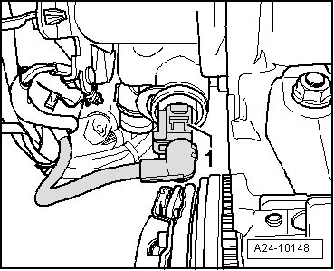
- Disconnect the electrical harness connector - 1 - from the Engine Coolant Temperature (ECT) Sensor (G62).
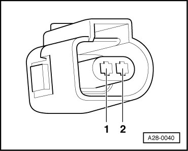
- Using jumper wire , bridge electrical connector terminals 1 + 2 together and observe indication on display.
If indication jumps to approx. 140.0° C:
- End diagnosis and switch ignition off.
- Replace Engine Coolant Temperature (ECT) Sensor ( G62).
If indication remains at approx. -40.0° C:
- Check the wiring for a short circuit to Battery positive (+) or an open circuit.
- If necessary, repair the wiring connection.
- End diagnosis and switch ignition off.
°Testing if display approx. 140.0 C:
- Disconnect the electrical harness connector - 1 - from the Engine Coolant Temperature (ECT) Sensor (G62).
If indication jumps to approx. -40.0° C:
- End diagnosis and switch ignition off.
- Replace Engine Coolant Temperature (ECT) Sensor ( G62).
- End diagnosis and switch ignition off.
If indication remains at approx. 140.0° C:
Checking wiring
- Using a Multimeter , check the following wiring connection for an open circuit.

Specified resistance 1.5 ohms max.
If the specification is not obtained:
- Check the wiring for a short circuit to Battery positive (+) or an open circuit.
- If necessary, repair the wiring connection.
If no malfunctions are found in the wiring:
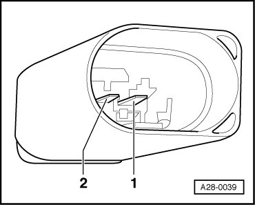
- Using a multimeter , check Engine Coolant Temperature (ECT) Sensor (G62) electrical connector terminals 1+2 for resistance.
• Area A: Resistance values for temperature range 0 to 50°C.
• Area B: Resistance values for temperature range 50 to 100°C.
Read-out examples:
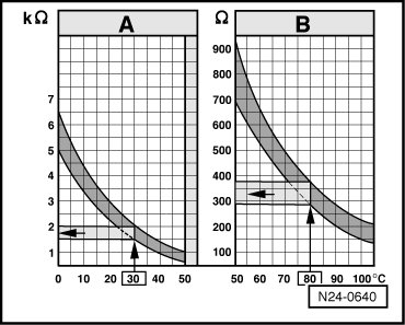
• 30° C is in range A and corresponds to a resistance of 1.5 to 2.0 kohms
• 80° C is in range B and corresponds to a resistance of 275 to 375ohms
If the specification is not obtained:
- Replace Engine Coolant Temperature (ECT) Sensor ( G62 ).
If the specification is obtained:
- Erase the DTC memory. Refer to => [ Diagnostic Mode 04 - Erase DTC Memory ] Diagnostic Mode 04 - Erase DTC Memory.
- Perform a road test to verify repair.
If the DTC does not return:
Repair complete, Generate readiness code. Refer to => [ Readiness Code ] Readiness Code.
- End diagnosis.
If the DTC does return and no malfunction is detected in the wiring and the voltage supply was OK:
- Replace the Engine Control Module (ECM) (J623 ) => [ Motronic Engine Control Module, Replacing ] Motronic Engine Control Module, Replacing.
Final procedures
After the repair work, the following work steps must be performed in the following sequence:
1. Check the DTC memory. Refer to => [ Diagnostic Mode 03 - Read DTC Memory ] Diagnostic Mode 03 - Read DTC Memory.
2. If necessary, erase the DTC memory. Refer to => [ Diagnostic Mode 04 - Erase DTC Memory ] Diagnostic Mode 04 - Erase DTC Memory.
3. If the DTC memory was erased, generate readiness code. Refer to => [ Readiness Code, Setting ] Readiness Code, Setting.
End of Diagnosis.