Information Bus: Testing and Inspection
Diagnostic Procedures
CAN-Bus, Checking Terminal Resistance
The Engine Control Module (ECM) communicates with all databus-capable control modules via a CAN databus.
These databus-capable control modules are connected via two data bus wires which are twisted together (CAN_High and CAN_Low), and exchange information (messages). Missing information on the databus is recognized as a malfunction and stored.
Trouble-free operation of the CAN-bus requires that it have a terminal resistance. This central terminal resistor is located in the Engine Control Module (ECM).
Special tools, testers and auxiliary items required
• Multimeter (VAG1526) or Multimeter (VAG1715)
• Connector test kit (VAG1594)
• Wiring diagram
Test requirements
• A CAN-bus malfunction was recognized via On Board Diagnostic (OBD) , Diagnostic mode 3: Check DTC memory.
• Ignition switched off.
Test sequence
- Connect test box to Engine Control Module (ECM) , connecting test box for wiring test. During this, wiring harness to Engine Control Module (ECM) is not connected.
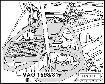
- Check central termination resistor in the Engine Control Module (ECM):
- To do this, measure resistance between test box sockets 58 + 60:
Specified value: 120 to 144 ohms
If resistance value is not in specified range:
- Replace Motronic Engine Control Module (ECM) (J220).
If resistance value is in specified range:
- Eliminate malfunction in Data-Bus wires or in other Data-Bus components according to wiring diagram:
Final Procedures
After the repair work, the following work steps must be performed in the following sequence:
1. Check the DTC memory. Refer to --> [ Diagnostic Mode 03 - Read DTC Memory ] Diagnostic Modes 01 - 09.
2. If necessary, erase the DTC memory. Refer to --> [ Diagnostic Mode 04 - Erase DTC Memory ] Diagnostic Modes 01 - 09.
3. If the DTC memory was erased, generate readiness code. Refer to --> [ Readiness Code ] Readiness Code.