Multi-Function Transmission Range Switch, Checking
Diagnostic Procedures
Multi-Function Transmission Range Switch, Checking
Special tools, testers and auxiliary items required
• Multimeter (VAG1526) or Multimeter (VAG1715)
• Connector test kit (VAG1594)
• Wiring diagram
Test requirements
• Respective fuses in fuse box must be OK:
• Control module with indicator unit in instrument cluster (J285) must be OK.
• Battery voltage must be at least 11.5 volts.
• All electrical consumers such as, lights and rear window defroster must be switched off.
• Parking brake must be engaged or else daylight driving lights will be switched on.
• Selector lever must be in P position.
• Ground (GND) connections to transmission must be OK.
Function test
- Switch ignition on.
- Depress brake pedal and maintain depressed.
- Shift into all selector lever positions.
• Selector lever position must correspond to display of Control module with indicator unit in instrument cluster (J285).
- Switch ignition off.
If selector lever position does not correspond to display of Control module with indicator unit in instrument cluster (J285)
- Check wires to Transmission Control Module (TCM) according to wiring diagram.
Checking wiring
- Connect test box to control module wiring harness , connect test box for wiring test.
- Disconnect 10-pin harness connector (arrow- 1 -) to Multi-Function Transmission Range (TR) Switch (F125).
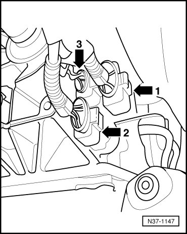
- Check wires between test box and 10-pin connector to Transmission Control Module (TCM) for open circuit according to wiring diagram.
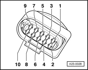
Terminal 1 + socket 47
Terminal 3 + socket 1
Terminal 4 + socket 2
Terminal 5 + socket 22
Terminal 7 + socket 10
Terminal 9 + socket 36
Terminal 10 + socket 21
Wire resistance: max. 1.5 ohms
- Check wires for short circuit to each other.
Specified value: infinite ohms
If no malfunctions are found in wires:
- Check adjustment of Multi-Function Transmission Range (TR) Switch (F125) , Multi-Function Transmission Range (TR) Switch, removing and installing, adjusting.
- Check adjustment of selector lever cable , Selector lever cable, adjusting.
- Erase DTC memory of Transmission Control Module (TCM) , Diagnostic mode 4: Reset/erase diagnostic data.
- Generate readiness code.
If no malfunctions are detected in wires and adjustments of selector lever cable and Multi-Function Transmission Range (TR) Switch are OK:
- Replace Multi-Function Transmission Range (TR) Switch (F125) , Multi-Function Transmission Range (TR) Switch, removing and installing, adjusting.
Final Procedures
After the repair work, the following work steps must be performed in the following sequence:
1. Check the DTC memory. Refer to --> [ Diagnostic Mode 03 - Read DTC Memory ] Diagnostic Modes 01 - 09.
2. If necessary, erase the DTC memory. Refer to --> [ Diagnostic Mode 04 - Erase DTC Memory ] Diagnostic Modes 01 - 09.
3. If the DTC memory was erased, generate readiness code. Refer to --> [ Readiness Code ] Readiness Code.