Cooling System
Coolant Hose Connection Diagram
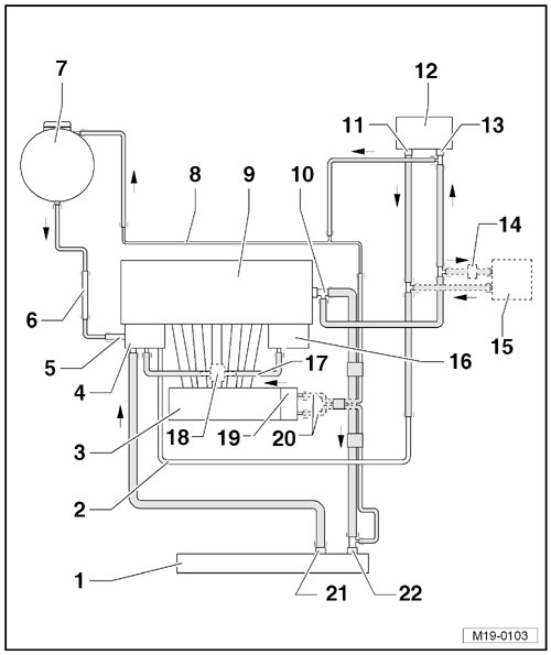
1 Radiator
• Removing and installing, refer to => [ Radiator ] Service and Repair.
• Replace coolant after replacing.
2 Coolant Pipe
3 Intake Manifold
4 Coolant Pump and Coolant Thermostat
• Coolant pump removing and installing. Refer to => [ Coolant Pump ] Service and Repair.
• Thermostat removing and installing. Refer to => [ Coolant Thermostat ] Coolant Thermostat.
• Checking the coolant thermostat, refer to - item 17 -=> [ Coolant Thermostat ] Cooling System Components, Engine Side.
5 Front Coolant Pipe
• Secured to the accessory bracket.
6 Right Coolant Pipe
• Secured to the engine mount.
7 Expansion Tank
• With sealing cap.
• Checking pressure relief valve in cap. Refer to => [ Checking the Pressure Relief
Valve in the Cap ] Cooling System, Checking For Leaks.
8 Rear Coolant Pipe
9 Cylinder Head/Cylinder Block
• Replace coolant after replacing.
10 Coolant Distribution Housing
11 Quick Release Coupling
• Lower connection.
12 Heater Core of Heater
• Replace coolant after replacing.
13 Quick Release Coupling
• Upper connection.
14 Bypass Thermostat
• Only for vehicles with a automatic transmission.
• Assembly overview, refer to => [ Bypass Thermostat Assembly
Overview ] Cooling System Components, Engine Side.
• Checking, refer to => [ Bypass Thermostat Checking ] Cooling System Components, Engine Side.
15 Automatic Transmission Fluid (ATF) Cooler
• Only for vehicles with a automatic transmission.
16 Oil Cooler
17 Coolant Hose
2 versions:
• Without engine pre-warming.
• With engine pre-warming.
18 Pre-Warmer
• Only on vehicles with engine pre-warming.
19 Throttle Valve Control Module (J338)
• Connection only for coolant heated throttle valve control module.
20 Coolant Hoses
• Only for the throttle valve control module heated by coolant.
21 Quick Release Coupling
• Upper connection
22 Quick Release Coupling
• Lower connection