Pistons and Connecting Rod Assembly Overview
Pistons and Connecting Rod Assembly Overview
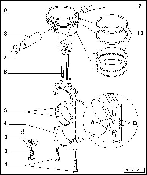
1 Bolt
• Replace
• 30 Nm + 90° (1/4) additional turn.
• Lubricate the threads and contact surface.
• Tighten to 30 Nm to measure radial play, do not turn further.
2 Pressure Relief Valve
• 27 Nm
• Opening pressure: 1.3 to 1.6 bar pressure.
3 Oil Spray Jet
• For piston cooling.
4 Connecting Rod Bearing Cap
• Note the installed position.
• Due to the separation procedure (cracking) for the connecting rod, the bearing cap only fits in one position and only on the appropriate connecting rod.
• Affiliation to the cylinder mark - B -.
• Installed position: marks - A - face the pulley side.
5 Bearing Shell
• Note the installed position, refer to.
• Do not interchange used bearing shells.
• Axial play new: 0.10 to 0.35 mm.
Wear limit: 0.4 mm.
• Measure radial clearance with Plastigage:
New: 0.02 to 0.06 mm.
Wear limit: 0.09 mm.
Do not turn the crankshaft when measuring radial play.
6 Connecting Rod
• With cracked bearing cap.
• Separating new connecting rods. Refer to => [ New Connecting Rod, Separating ] Procedures.
• Only replace as a set.
• Affiliation to the cylinder mark - B -.
• Installed position: marks - A - face the pulley side.
7 Circlip
8 Piston Pin
• If difficult to move, heat piston to 60 °C (140 °F).
• Remove and install using a pilot drift (VW 222A).
9 Piston
• Checking, refer to => [ Pistons, Checking ] Piston, Rings and Cylinder Bore, Checking.
• Mark the installed position and cylinder allocation.
• Arrow on piston face points toward the belt pulley side.
• Install with a piston ring compressor.
• Checking cylinder bore, refer to => [ Cylinder Bore, Checking ] Piston, Rings and Cylinder Bore, Checking.
• Piston and cylinder dimensions. Refer to => [ Piston and Cylinder Dimensions ] Piston and Cylinder Dimensions.
10 Piston Rings
• Offset gaps by 120°
• Use piston ring pliers for removal and installation.
• Marks face toward the piston crown.
• Checking ring gap, refer to => [ Piston Ring Gap, Checking ] Piston, Rings and Cylinder Bore, Checking.
• Checking piston ring groove clearance, refer to => [ Piston Ring Groove
Clearance, Checking ] Piston, Rings and Cylinder Bore, Checking.
Bearing Shell, Installed Position
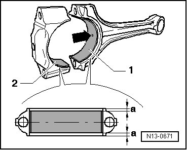
Bearing shell - 1 - with connecting rod oil bore - arrow -.
Bearing shell - 2 - without oil bore for connecting rod cap.
- Place bearing shells centrally into the connecting rod and cap.
Dimension - a - must be the same on the left and right.