Ignition System Assembly Overview
Ignition System Assembly Overview
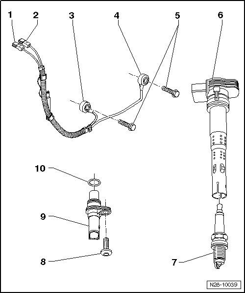
1 Harness connector for Knock Sensor (KS) 2 (G66 )
• Gray
• Contacts gold plated
• Installed location => [ Installation position of harness connectors
for knock sensors ]
2 Harness connector for Knock Sensor (KS) 1 (G61 )
• Green
• Contacts gold plated
• Installed location => [ Installation position of harness connectors
for knock sensors ]
3 Knock Sensor (KS) 2 (G66)
• Note installation position: Cable connection points 45° toward right on outside
4 Knock Sensor (KS) 1 (G61)
• Note installation position: Cable connection points downward vertically.
5 20 Nm
• Tightening specifications affects function of Knock Sensor (KS).
6 Ignition coil with power output stage (N70, N127, N291, N292, N323)
• Removing and installing => [ Ignition Coils with Power Output Stages ] Service and Repair
7 Spark plug
• 25 Nm
• Type and electrode gap => [ Spark Plug Test Data ] Spark Plug Test Data
• Removing and installing with spark plug removal tool (3122 B)
8 10 Nm
9 Camshaft Position (CMP) sensor (G40)
• Contacts gold plated
10 O-ring
• Replace if damaged
Installation position of harness connectors for knock sensors
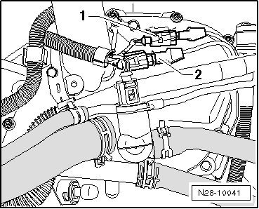
1. Green for Knock Sensor (KS) 1 (G61)
2. Gray for Knock Sensor (KS) 2 (G66)