Component Location Overview
Component Location Overview
ABS/ESP
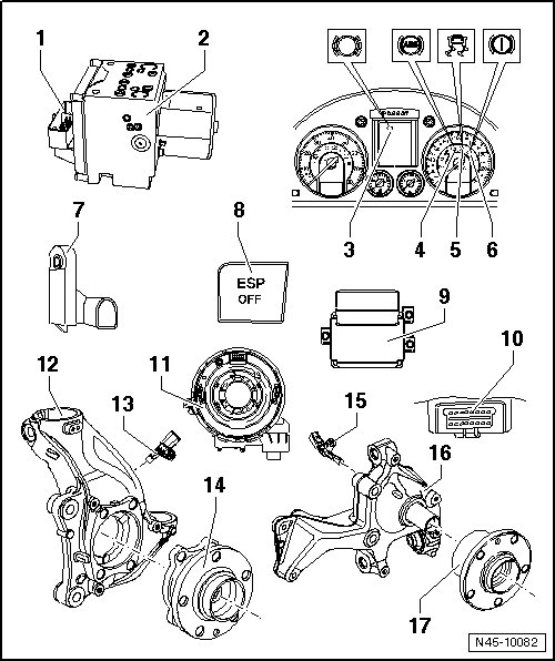
1 ABS Control Module (J104)
• Component location: At hydraulic unit on right side of engine compartment.
• Do not disconnect connector before successfully completing On Board Diagnostic (OBD). Turn the ignition off before separating connector.
• Must not be separated from the ABS hydraulic unit (N55)
• Removing and installing, refer to => [ Control Module and Hydraulic Unit ] Service and Repair
2 ABS Hydraulic Unit (N55)
• Component location: in engine compartment, right
The hydraulic unit consists of the following components:
• Brake pressure sensor (G201)
• ABS hydraulic pump (V64)
• Valve block (contains inlet and outlet valves)
• The ABS hydraulic pump (V64) and valve block must not be separated from one another
• Must not be separated from the ABS control module
• Removing and installing, refer to => [ Control Module and Hydraulic Unit ] Service and Repair
3 Brake Pad Wear Indicator Lamp (K32)
• Component location: Inside the instrument cluster
4 ABS Indicator Lamp (K47)
• Component location: Inside the instrument cluster
5 ASR/ESP Indicator Lamp (K155)
• Component location: Inside the instrument cluster
6 Brake System Indicator Lamp (K118)
• Component location: Inside the instrument cluster
7 Brake Lamp Switch (F)
• Component location: On brake master cylinder
• Removing and installing, refer to => [ Brake Lamp Switch (F) ] Service and Repair
8 ASR/ESP Button (E256)
• Component location: Inside center console
9 ESP Sensor Unit (G419) and Electromechanical Parking Brake Control Module (J540)
• Component location: Beneath center console
• Combined transverse acceleration sensor (G200) , rotation rate sensor (G202) and longitudinal acceleration sensor (G251)
• Installed together in one housing with the electromechanical parking brake control module.
• Removing and installing, refer to => [ ESP Sensor Unit (G419) ] Service and Repair
10 Data Link Connector (DLC)
• Component location: driver side footwell cover
11 Steering Angle Sensor (G85)
• Component location: On steering column between steering wheel and steering column switch
• Removing and installing, refer to => [ Steering Angle Sensor (G85) ] Service and Repair
12 Wheel Bearing Housing
13 Right Front ABS Wheel Speed Sensor (G45) / Left Front ABS Wheel Speed Sensor (G47)
• Removing and installing, refer to => [ Front Axle Speed Sensor Overview ] Front Axle Speed Sensor Overview
14 Wheel Hub with Wheel Bearing
• The ABS sensor ring is installed in the wheel bearing
15 Right Rear ABS Wheel Speed Sensor (G44) / Left Rear ABS Wheel Speed Sensor (G46)
• Removing and installing, refer to => [ Rear Axle Speed Sensor Overview ] Rear Axle Speed Sensor Overview
16 Wheel Bearing Housing
Front wheel drive shown
17 Wheel Hub with Wheel Bearing
Front wheel drive shown
• The ABS sensor ring is installed in the wheel bearing