Antilock Brakes / Traction Control Systems: Service and Repair
ABS Control Module and Brake Booster Overview
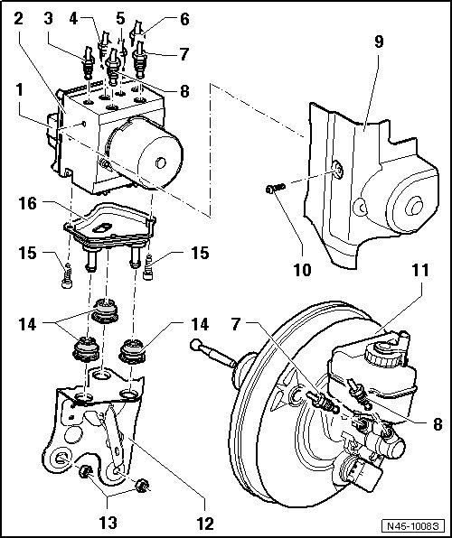
1 ABS Control Module (J104)
It is not possible to separate the control module and hydraulic unit.
• Removing and installing, refer to => [ Control Module and Hydraulic Unit ] Service and Repair
2 ABS Hydraulic Unit (N55)
It is not possible to separate the control module and hydraulic unit.
• Removing and installing, refer to => [ Control Module and Hydraulic Unit ] Service and Repair
3 Brake Line
• To the right front brake caliper
• Identification: 5.25 mm diameter and tube fitting with M10 x 1 thread
• Marked on hydraulic unit with "VR"
4 Brake Line
• To left rear brake caliper
• Identification: 5.25 mm diameter and tube fitting with shorter thread M12 x 1
• Marked on hydraulic unit with "HL"
5 Brake Line
• To the right rear brake caliper
• Identification: 5.25 mm diameter and tube fitting with M10 x 1 thread
• Marked on hydraulic unit with "HR"
6 Brake Line
• To left front brake caliper
• Identification: 5.25 mm diameter and tube fitting with shorter thread M12 x 1
• Marked on hydraulic unit with "VL"
7 Brake Line
• Master brake cylinder/primary piston circuit to hydraulic control unit
• Identification: 8.5 mm or 6 mm and tube fitting with longer thread M12 x 1
• Marked on hydraulic unit with "HZ1"
8 Brake Line
• Master brake cylinder/secondary piston circuit to hydraulic unit
• Identification: 8.5 mm or 6 mm and tube fitting with longer thread M12 x 1
• Marked on hydraulic unit with "HZ2"
9 Heat Shield
10 Inner TORX(R) Bolt
• 12 Nm
11 Brake Booster
• On vehicles with a hydraulic brake booster, a vacuum sensor is installed, refer to => [ Brake Booster Vacuum Sensor (G483) ] Brake Booster Vacuum Sensor (G483)
• Removing and installing, refer to => [ Brake Booster ] Brake Booster
12 Bracket
13 Nut
• 20 Nm
14 Rubber Insulation
15 Inner TORX(R) Bolt
• 10 Nm
16 Bracket