Subframe, Stabilizer Bar and Lower Control Arm Overview
Subframe, Stabilizer Bar and Lower Control Arm Overview
• Welding and straightening work on supporting or wheel carrying components of the suspension is not permitted.
• Always replace self-locking nuts.
• Always replace corroded bolts and nuts.
• Bonded rubber bushings can only be turned to a limited extent. Therefore tighten threaded connections for components with bonded rubber bushings only when the wheel bearing housing has been lifted (curb weight position). Refer to => [ Front Subframe ] Front Subframe.
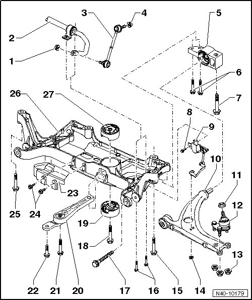
1 Nut
• 65 Nm
• Always replace if removed.
• Self-locking.
• Counter hold the stud socket head when tightening.
2 Stabilizer Bar
• There are different versions.
• Allocation, refer to the Parts Catalog.
• Removing and installing, refer to => [ Stabilizer Bar ] Stabilizer Bar.
3 Coupling Rod
• Linking the stabilizer bar to the strut.
4 Nut
• 65 Nm
• Always replace if removed.
• Self-locking
• Counter hold the stud socket head when tightening.
5 Lower Control Arm Bracket
• Locating, refer to => [ Lower Control Arm Bracket, Securing ] Subframe, Securing.
• With a bonded rubber bushing.
6 Bolt
• M10 x 70
• 50 Nm + an additional 90°(1/4) turn.
• Always replace if removed.
7 Bolt
• M12 x 1.5 x 100
• 70 Nm + an additional 180° (1/2) turn.
• Always replace if removed.
8 Bolt
• M6 x 16
• 9 Nm
9 Left Front Level Control System Sensor (G78)
• Removing and installing, refer to => [ Front Level Control System Sensors G78/G289 ] Front Level Control System Sensors G78/G289.
• Can be checked in Guided Fault Finding using the vehicle diagnostic tester.
10 Control Arm
• Replace with the ball joint if damaged.
• Removing and installing, refer to one of the following:
=> [ Lower Control Arm ] Lower Control Arm.
=> [ Lower Control Arm, Left Side, for Vehicles with a DSG(R) or Automatic Transmission ] Lower Control Arm, Left Side, for Vehicles with a DSG(R) or Automatic Transmission.
• Bushing replacing, refer to => [ Lower Control Arm Bonded Rubber Bushing ] Procedures.
• It is possible there are different versions of the control arm (steel, sheet steel, aluminum).
• Allocation, refer to the Parts Catalog.
• Ensure that the control arm being installed is of the same version/material as the control arm on the opposite side.
11 Nut
• M12 x 1.5
• 60 Nm
• Self-locking
• Always replace if removed.
12 Ball Joint
• Checking, refer to => [ Ball Joint, Checking ] Procedures.
• Removing and installing, refer to => [ Ball Joint ] Removal and Replacement.
• Replace with the control arm if damaged.
13 Nut
• Cast steel control arm: 60 Nm.
• Steel and aluminum control arms: 100 Nm.
• Self-locking.
• Always replace if removed.
14 Nut
• 9 Nm
15 Bolt
• M12 x 1.5 x 100: 70 Nm + an additional 180° (1/2) turn.
• M12 x 1.5 x 110: 70 Nm + an additional 90° (1/4) turn.
• Always replace if removed.
16 Bolt
• M8 x 55
• 20 Nm + an additional 90° (1/4) turn.
• Always replace if removed.
17 Bolt
• M12 x 1.5 x 110
• 70 Nm + an additional 180° (1/2) turn.
• Always replace if removed.
• Tighten only in curb weight position. Refer to => [ Front Subframe ] Front Subframe.
18 Bolt
• M14 x 1.5 x 70
• 100 Nm + an additional 90° (1/4) turn.
• Only tighten when the pendulum support is bolted to the transmission.
• Always replace if removed.
19 Bonded Rubber Bushing for the Pendulum Support
• Removing and installing, refer to => [ Subframe Bonded Rubber Bushings ] Service and Repair.
• There are different versions, refer to => [ Identifying the Pendulum Support Bonded Rubber Bushing ].
20 Pendulum Support
• First, secure to the transmission, then to the subframe.
• There are different versions.
• Allocation, refer to the Parts Catalog.
21 Bolt
• M10 x 75: 50 Nm + an additional 90° (1/4) turn.
• M12 x 1.5 x 85: 60 Nm + an additional 90°(1/4) turn.
• Always replace if removed.
22 Bolt
• M10 x 35
• 50 Nm + an additional 90° (1/4) turn.
• Always replace if removed.
23 Heat Shield
• On Front Wheel Drive (FWD) vehicles only.
24 Bolt
• 6 Nm
25 Bolt
• M12 x 1.5 x 90
• 70 Nm + an additional 180° (1/2) turn.
• Always replace if removed.
26 Subframe
• Removing and installing without the steering gear. Refer to => [ Subframe, without the Steering Gear ] Subframe, without the Steering Gear.
• Removing and installing with the steering gear. Refer to => [ Subframe, with the Steering Gear ] Subframe, with the Steering Gear.
• There are different versions.
• Allocation, refer to the Parts Catalog.
27 Bonded Rubber Bushing for the Pendulum Support
• Removing and installing, refer to => [ Subframe Bonded Rubber Bushings ] Service and Repair.
• There are different versions, refer to => [ Identifying the Pendulum Support Bonded Rubber Bushing ].
Identifying the Pendulum Support Bonded Rubber Bushing
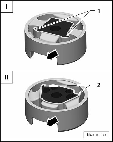
• There are two different versions of the pendulum support bonded rubber bushing: the T version - I - and the V version - II -.
• Allocation, refer to the Parts Catalog.
I The corners on the inner core - 1 - face toward the opening for the pendulum support - arrow - (T version).
II The corners on the inner core - 2 - face away from the opening for the pendulum support - arrow - (V version).