Body Control Module: Service and Repair
Comfort System Central Control Module (J393)
Special tools, testers and auxiliary items required
• Torque Wrench (V.A.G 1410)
• If Comfort System Central Control Module is to be replaced, the work procedure => [ Comfort System Central Control Module, Replace and Coding ] Programming and Relearning to read out the codes stored in the module must always be performed.
• After replacing Comfort System Central Control Module, other functions of Comfort System Central Control Module such as Anti-theft Immobilizer, Anti-theft Alarm System, access and start authorization, tire pressure monitoring and central locking system key must also be adapted, depending on vehicle equipment.
• In this case, start by adapting the Anti-theft Immobilizer. Refer to => [ Anti-Theft Immobilizer Control Module, Adapting ] Anti-Theft Immobilizer Control Module (J362), Adapting and then the other equipment-dependent functions of comfort system central control module in any order.
Removing:
- Switch ignition and all electrical consumers off and disengage the key or ignition switch in position 0 (ignition off).
- Remove the glove compartment.
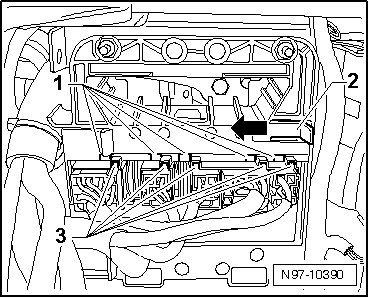
- Pull retaining tab - 2 - on the comfort system central control module bracket in the - direction of the arrow - and slide the comfort system central control module until recesses - 1 - and - 3 - line up.
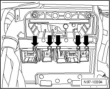
• The connectors can only be disengaged and disconnected when the recesses - arrows - of the connectors and bracket line up exactly.
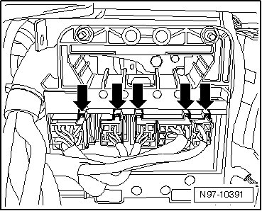
- Release and disconnect the connectors from the comfort system central control module.
• The number of connectors depends on the vehicle equipment.
• All connectors can only be connected in one position and therefore do not need to be labeled.
- Remove the nuts - arrows -.
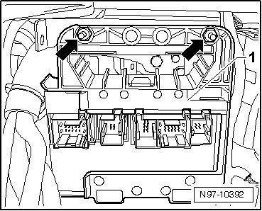
- Remove bracket with comfort system central control module - 1 -.
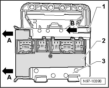
- Pull retaining tab - 1 - in - direction of arrow B - and slide comfort system central control module - 2 - out of bracket - 3 - in - direction of arrow A -.
Installing:
Install in reverse order of removal, noting the following:
- Tighten the nuts to tightening specification. Refer to => [ Fastener Tightening Specifications, Comfort System Central Control Module ] [1][2]Body Control Module.
• The connectors can only be connected and locked when the recesses - arrows - of the connectors and bracket line up exactly.