Electronic Brake Control Module: Service and Repair
Control Module and Hydraulic Unit
Special tools, testers and auxiliary items required
• Torque wrench (V.A.G 1331)
• Torque wrench (V.A.G 1410)
• Brake Pedal Actuator (V.A.G 1869/2)
Sealing Plug from Repair Kit 1H0 698 311 A
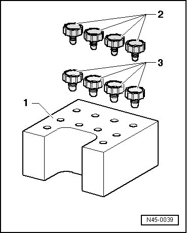
1 Transport protection for valve domes (foam)
2 Sealing plug M 10
3 Sealing plug M 12
Removing
Component location:
The control module is bolted to the hydraulic unit and is located at right in the engine compartment.
CAUTION!
Do not bend the brake lines near the hydraulic unit.
- Read and note the present control module coding.
- If the vehicle has a coded radio, get the radio code from the customer before beginning.
- Disconnect battery.
- Remove engine cover.
With a 3.6 L Engine
- Disconnect knock sensor and vacuum hose valve connectors at rear of intake manifold. Unclip wiring harness from retainers on coolant pipe and lay it aside.
- Remove vacuum hoses on rear of intake manifold, remove from retainers and set aside completely.
- Loosen right rear coolant pipe from left and rear of engine.
- Disconnect both coolant hoses on reservoir with hose clamps up to 25 mm dia. (3094).
- Now remove both coolant hoses on reservoir and then set them as far aside as possible with coolant pipe.
All Vehicles
- On vehicles with heat shield, remove heat shield.
- Press the red securing clip in direction of - arrow - toward the rear.
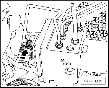
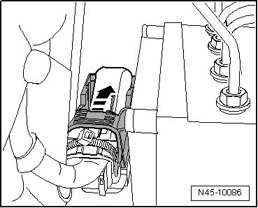
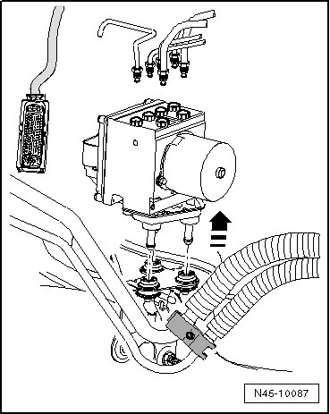
- Release and remove connector from control module in direction of - arrow -.
- Insert (V.A.G 1869/2).
- Attach bleeder hose of bleeder bottles to left-front and left-rear brake caliper bleeder valves and open bleeder valves.
- Operate brake pedal using (V.A.G 1869/2) at least 60 mm.
- Close left front and left rear bleeder valves.
- Do not remove (V.A.G 1869/2).
- Place sufficient lint-free cloths under the control module and hydraulic unit.
Make sure that brake fluid does not come in contact with the terminals.
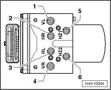
- First, mark both brake lines from master cylinder and remove from the hydraulic unit.
- Plug the brake lines and threaded holes immediately with sealing plugs from the repair kit Part No. 1H0 698 311 A.
- Mark, unfasten and plug the remaining brake lines (brake calipers).
- Lift the hydraulic unit with control module up and out of the dampers - arrow -.
Installing
• Do not remove sealing plugs at new hydraulic unit until the corresponding brake line is about to be installed.
• If the sealing plugs are removed too early, brake fluid can escape and unit may not be sufficiently filled or adequately bled.
• When installing the hydraulic unit, make sure the damper rubber is not pushed out of the bracket.
- Installation is in reverse order of removal.
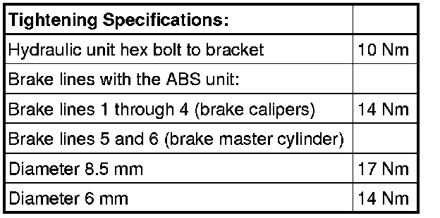
Fastening sequence of brake lines:
- Remove (V.A.G 1869/2).
- Bleed brake system. Refer to => [ Brake System, Bleeding ] Brake System, Bleeding.
- Enter radio code.
- Code the ABS Control Module (J104) with the in guided fault finding.
A steering angle sensor (G85), transverse acceleration sensor (G200), longitudinal acceleration sensor (G251) and brake pressure sensor 1 (G201) basic setting must be done.