Relay Carrier on Vehicle Electrical System Control Module (J519)
Relay Carrier on Vehicle Electrical System Control Module (J519)
• The Vehicle Electrical System Control Module and relay carrier on Vehicle Electrical System Control Module are one component and cannot be replaced separately.
• If Vehicle Electrical System Control Module or relay carrier is to be replaced, the work procedure => [ Vehicle Electrical System Control Module, Coding ] Programming and Relearning to read out the codes stored in the module must always be performed.
Removing:
- Switch ignition and all electrical consumers off and disengage the key or ignition switch in position 0 (ignition off).
- Remove foot well cover on driver's side.
- Slide connector securing latch - 1 - of the relay carrier on the vehicle electrical system control module in the - direction of the arrow -.
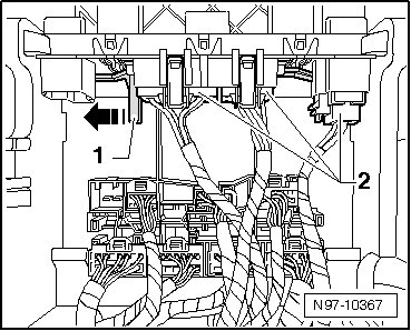
• The connectors of the relay carrier on the vehicle electrical system control module can only be disconnected when the securing latch is in the OPEN position.
• The number of connectors and therefore relays depends on the vehicle equipment.
• All connectors can only be connected in one position and therefore do not need to be labeled.
- Release connectors - 2 - and disconnect them.
- Slide securing latch - 1 - of harness connectors of Vehicle Electrical System Control Module in - direction of arrow -.
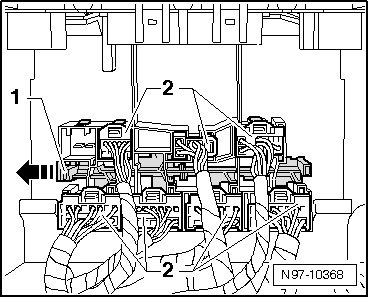
• The connectors of the vehicle electrical system control module can only be disconnected when the securing latch has been set to the OPEN position beforehand.
• The number of connectors on the vehicle electrical system control module depends on the vehicle equipment.
• All connectors can only be connected in one position and therefore do not need to be labeled.
- Release connectors - 2 - and disconnect them.
- Clip vehicle electrical system control module and relay carrier at vehicle electrical system control module out of locking devices - arrows C -.
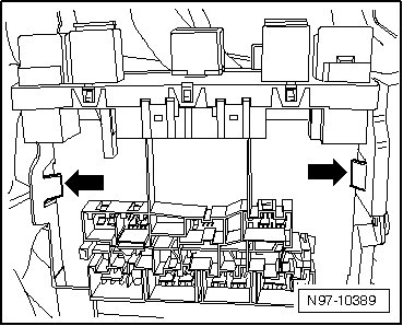
- Pull vehicle electrical system control module and relay carrier at vehicle electrical system control module downward and out of bracket in opposite direction of travel.
Installing:
Install in reverse order of removal, noting the following:
• The securing latch can only be brought into the CLOSED position when all connectors are correctly connected.