Through Model Year 2011
No Response from Powertrain Control Module
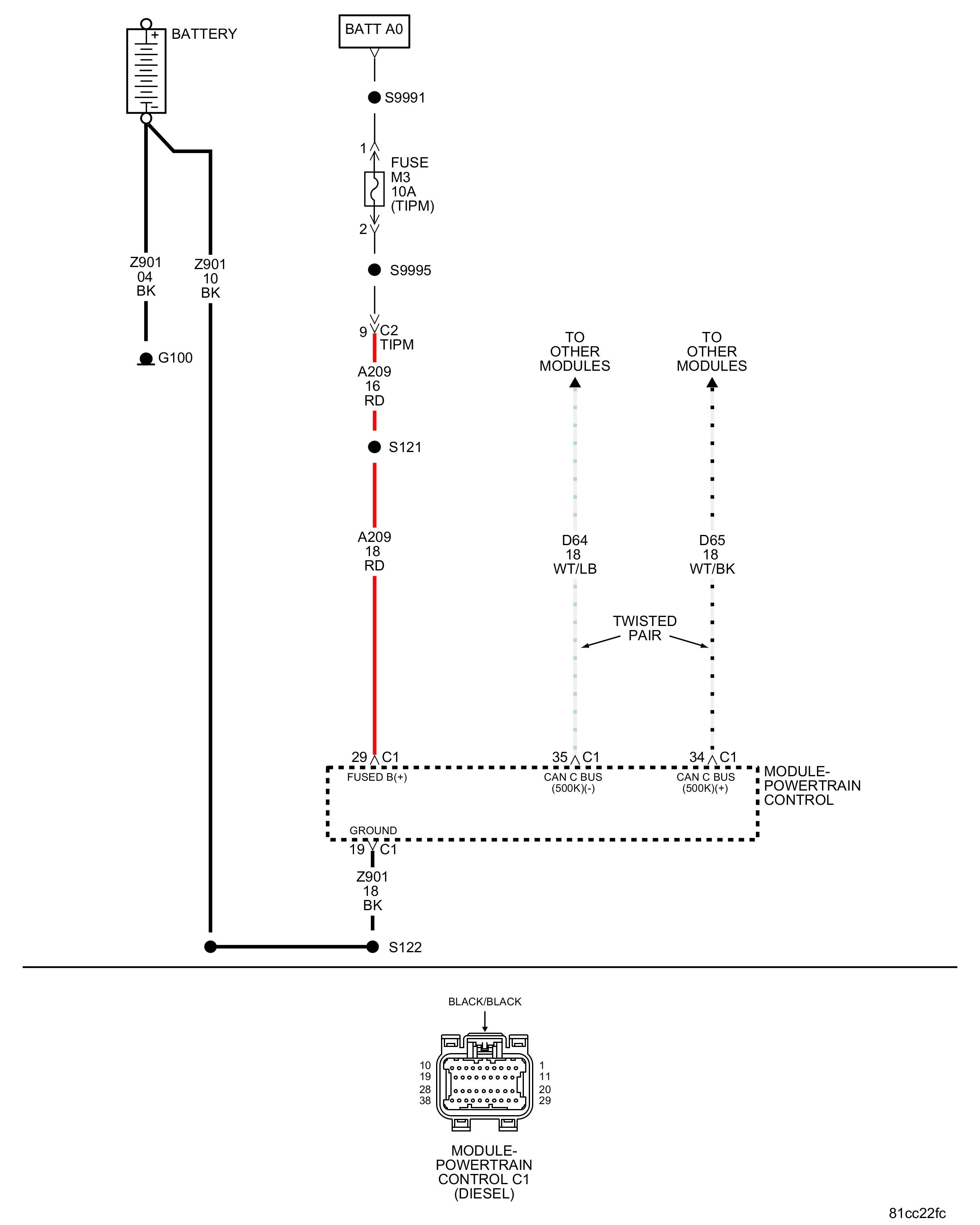
For a complete wiring diagram, refer to.
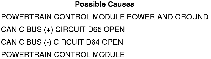
Test Step 1 - Test for Intermittent Condition
• Check for any TSBs related to the condition. Perform any applicable procedures outlined in the TSBs before continuing.
• Turn the ignition on.
• Ensure the IOD fuse is installed and battery voltage is between 10.0 and 16.0 volts.
• With the scan tool, select ECU view.
• A red X will be next to the module that is not communicating, indicating that the module is not active on the bus network. A green check indicates that the module is active on the bus network.
• Check the totally integrated power module for any active CAN C hardware DTCs, resolve the DTCs before proceeding.
Does the scan tool display a red X next to the module?
Yes
• Go to Test Step 2
No
• The no response condition is not present at this time. Using the wiring diagram/schematic as a guide, inspect the wiring for chafed, pierced, pinched, and partially broken wires and the wiring harness connectors for broken, bent, pushed out, and corroded terminals.
• Perform the Powertrain Verification Test. Refer to => [ PCM Verification Test ] PCM Verification Test
Test Step 2 - Attempt to Communicate with the PCM
• With the scan tool in ECU View, observe the status of the PCM.
Does the scan tool display a red X next to the PCM?
Yes
• Perform the No Response from PCM diagnostic procedure. Refer to => [ No Response from Powertrain Control Module ] No Response from Powertrain Control Module
No
• Go to Test Step 3
Test Step 3 - CAN C Bus (+) Circuit Open
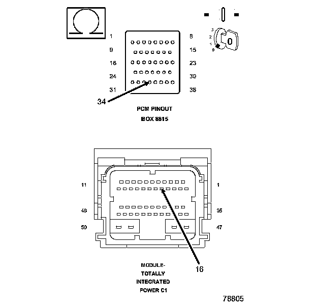
• Turn the ignition off.
• Disconnect the TIPM C1 harness connector.
• Measure the resistance of the CAN C bus (+) circuit between the TIPM connector and the appropriate terminal of the special tool #8815.
Is the resistance less than 5.0 ohms?
Yes
• Go to Test Step 4
No
• Repair the CAN C bus (+) circuit for an open.
• Perform the Powertrain Verification Test. Refer to => [ PCM Verification Test ] PCM Verification Test
Test Step 4 - CAN C Bus (-) Circuit Open
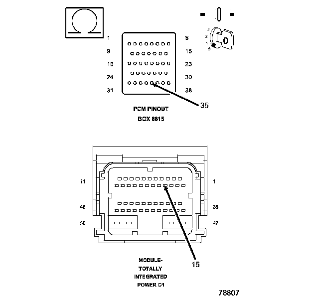
• Measure the resistance of the CAN C bus (-) circuit between the TIPM connector and the appropriate terminal of the special tool #8815.
Is the resistance less than 5.0 ohms?
Yes
• Replace and program the PCM.
• Perform the Powertrain Verification Test. Refer to => [ PCM Verification Test ] PCM Verification Test.
No
• Repair the CAN C bus (-) circuit for an open.
• Perform the Powertrain Verification Test. Refer to => [ PCM Verification Test ] PCM Verification Test.