Subframe, Removing and Installing
Subframe, Removing and Installing
Special tools, testers and auxiliary items required
• Torque wrench (V.A.G 1332)
• Tensioning straps (T10038)
• Engine/transmission jack (V.A.G 1383 A) with universal transmission support (V.A.G 1359/2)
• Locating fixtures (T10096)
Removing
• Be aware that if there is additional work where the drive axle twelve point bolt must be loosened, this must also occur with the vehicle resting on the wheels. Twelve-Point Bolt With Ribs, Loosening, refer to => [ Drive Axle Twelve-Point Bolt with Ribs, Loosening and Tightening ] . Twelve-Point Bolt Without Ribs, Loosening, refer to => [ Drive Axle Twelve-Point Bolt without Ribs, Loosening and Tightening ] .
- Remove wheels.
- Remove coil springs. Refer to => [ Coil Spring ] .
- Remove exhaust system rear muffler.
- Disconnect electrical connections between subframe and body.
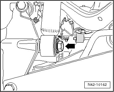
- Remove bolt - arrow -.
- Remove the clip - 1 -.
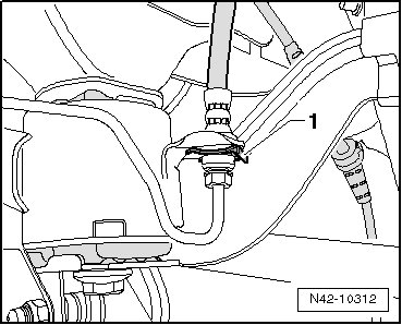
• Do not disconnect the brake line.
- Disconnect electrical parking brake connections at brake caliper.
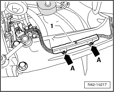
- Remove retainer - 1 -, pressing out inner pins of rivets - arrows A -.
- Remove line - 1 - at mounting bracket - arrow A -.
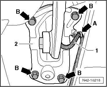
- Mark installation position of mounting bracket - 2 - on body.
- Remove bolt - B arrows -.
- Disconnect left rear level control system sensor (G76) connector.
- Check whether there is a marking (colored point) - arrows - on joint washer or final drive flange. If there is no mark, mark position of joint washer and final drive flange to each other - arrows -.
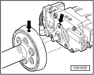
- Disconnect Right Rear ABS Wheel Speed Sensor (G44) and Left Rear ABS Wheel Speed Sensor (G46) connectors.
- Remove rear driveshaft tube from rear final drive with joint washer and vibration damper - arrows -.
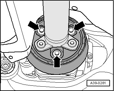
- Remove the center bracket bolts - arrows - two turns.
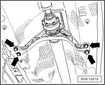
- Support the driveshaft - A - on the tunnel support - 1 - with a wood block.
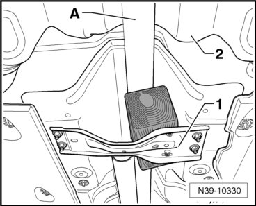
- Move rear driveshaft tube as far as possible in direction of transmission.
- Disconnect connector to Haldex clutch above final drive.
- Now secure vehicle on both sides to lifting arms on hoist with (T10038).
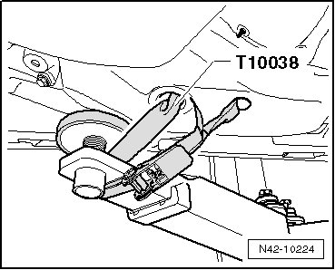
If vehicle is not secured, it could slide off of hoist.
- Place (V.A.G 1383 A) with (V.A.G 1359/2) below subframe and secure with strap.
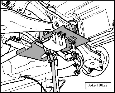
To locate subframe, (T10096) must be screwed in one after the other on both sides of the vehicle at positions - 1 - and - 2 -.
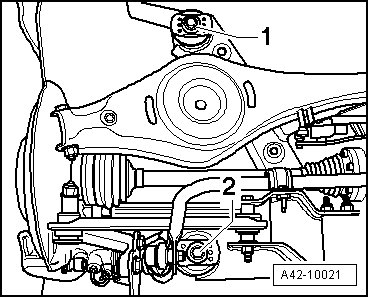
- Remove hex head screw - 1 - or - 2 - on both sides.
• For the sake of a better illustration, only the left side of the vehicle is shown.
- Location position of subframe with (T10096).
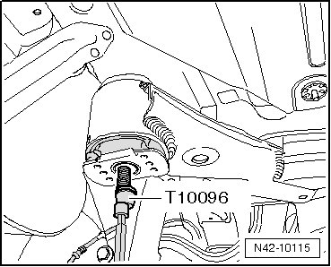
• (T10096) may only be tightened to a maximum of 20 Nm, since otherwise the threads of the locating bolts will be damaged.
- Replace subframe bolts one after the other on both sides using (T10096) and tighten them to 20 Nm.
Position of subframe is now secured.
- Carefully lower the subframe with its components approximately. 2 cm.
- Unclip the brake line on both sides - arrow -.
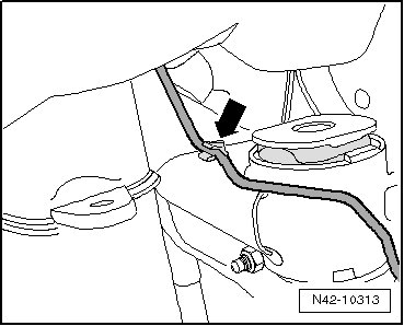
• When doing this, the clips will be destroyed and must be replaced.
- Remove the brake line above the drive axle flange on the transmission- 1 - from the clips - arrows -.
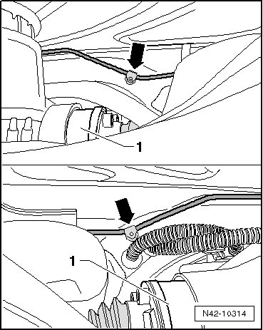
• When doing this, the clips will be destroyed and must be replaced.
- Carefully lower subframe with components.
• Make sure there is enough clearance for brake lines, electrical lines and driveshaft centering pin when lowering.
Installing
Install in reverse order of removal. Observe the following when doing so:
• Replace the destroyed brake line clips on the subframe.
- When installing the wires for the electrical parking brake, make sure the dimension - a - between the connector - 1 - and the retainer - 2 - is exact.
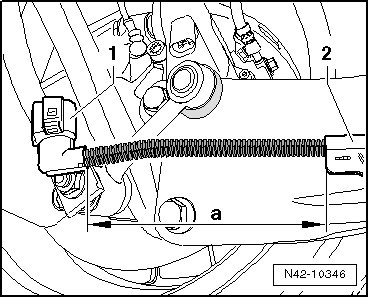
Dimension - a - = 150 mm
Connect the driveshaft to the rear axle drive.
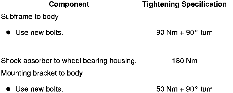
Tightening Specifications