Fuel System, Checking for Leaks
Fuel System, Checking for Leaks
=> [ Fuel System Leak Test ]
=> [ EVAP System Function Overview ]
=> [ Leak Detection Pump, Checking Vacuum Supply ]
Special tools, testers and auxiliary items required
• Evaporative Emission Tester (KLI 9210)
• Adapter for Evaporative Emission Tester (KLI 9210/55-1)
• Vehicle Diagnostic Tester
• Hose Clamps Up to 25 mm Dia. (3094)
The connectors for fuel, vacuum and ventilation lines are marked with colors. There is either a colored dot on the connector or the release button is the corresponding color.
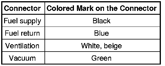
Test Conditions:
• A leak was detected by the leak detection pump (V144).
• Guided fault finding was performed using the vehicle diagnostic tester.
Evaporative Emissions Tester (KLI 9210) Preparation:
• Depending on the version, the appearance of the evaporative emissions tester (KLI 9210) may vary.
- Check the evaporative emissions tester (KLI 9210) to determine whether there is enough fluid in the smoke generator.
- Set the valve - D - to "Hold".
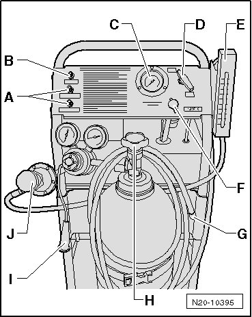
- Open the nitrogen bottle - H -.
- Connect the measuring hose - G - to the self-test connection - B -.
- Set the valve - D - to "Test".
- Using the pressure reducer - J -, adjust the pressure to 10 in. H2O (25 mbar).
- Set the valve - D - to "Hold".
- The pressure must now be maintained a minimum of 2 minutes. If the pressure is not maintained, check the tester.
Fuel System, Checking for Leaks:
- Connect the adapter for evaporative emission tester (KLI 9210/55-1) to the ventilation line - A - as shown. (color identification: white)
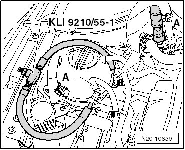
- Connect the measuring hose - G - from the evaporative emissions tester (KLI 9210) to the adapter for evaporative emission tester (KLI 9210/55-1).
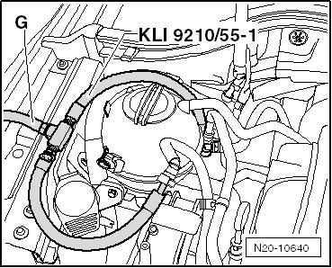
- Set the valve - D - to "Hold".
- Connect the vehicle diagnostic tester to the vehicle.
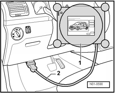
- Start the engine and run at idle speed.
- Select Guided Functions on the vehicle diagnostic tester.
- Select "Check tank ventilation system for leaks" guided function.
- Activate the test.
- While the test runs, observe the pressure gauge on the evaporative emissions tester (KLI 9210).
• The leak detection pump must pump the fuel system pressure up to at least 7 in. H2O (18 mbar).
The minimum pressure is not reached, but the pressure reached does not decrease:
- Turn the ignition off and perform a pressure retention test. If no decrease in pressure is observed: Check the leak detection pump vacuum supply. Refer to => [ Leak Detection Pump, Checking Vacuum Supply ].
The minimum pressure is not reached and the pressure reached decreases immediately:
- Clamp off the hose to the EVAP canister purge regulator valve 1 (N80) using the hose clamps up to 25 mm dia. (3094) - arrow -.
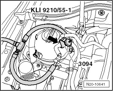
- Repeat the test. If the minimum pressure is not reached: Replace the EVAP canister purge regulator valve 1.
The minimum pressure is not reached again and the pressure reached decreases immediately:
- There is a leak in the fuel system: perform "fuel system leak test". Refer to => [ Fuel System Leak Test ].
If the minimum pressure is reached, turn the ignition off.
The valve in the leak detection pump is now closed and the pressure is maintained.
- Observe the pressure gauge:
If the pressure does not decrease, perform a pressure retention test to locate any possible pinhole leaks.
If the pressure decreased, clamp off the hose to the EVAP canister purge regulator valve 1 using the hose clamps up to 25 mm dia. (3094) - arrow -.
- If pressure now no longer falls, replace the EVAP canister purge regulator valve 1.
If the pressure still decreases, perform the "fuel system leak test". Refer to => [ Fuel System Leak Test ].
Pressure Retention Test
- Set the valve - D - to "Test". Increase the present pressure to 10 in. H2O (25 mbar).
- Observe the pressure gauge - C - and flow meter - E -. The fuel system is filled if the flow quantity decreases and the pressure increases to 10 in. H2O (25 mbar).
• Depending on the level in the fuel tank, this procedure may take up to 3 minutes.
- After the pressure has stabilized, set the valve - D - to "Hold".
• After 5 minutes the pressure must not drop below 8 in. H2O (20 mbar).
If the pressure is not maintained for 5 minutes, the leak should be localized as follows:
- First, check the EVAP canister purge regulator valve 1 for leaks. Clamp off the hose to the EVAP canister purge regulator valve 1 using the hose clamps up to 25 mm dia. (3094) - arrow -.
- Repeat the pressure test by resetting the valve - D - to "Test".
- Observe the pressure gauge - C - and flow meter - E -. The fuel system is filled if the flow quantity decreases and the pressure increases to 10 in. H2O (25 mbar).
- After the pressure has stabilized, set the valve - D - to "Hold".
- If the pressure now no longer falls, replace the EVAP canister purge regulator valve 1.
If the pressure still decreases, perform the "fuel system leak test". Refer to => [ Fuel System Leak Test ].
After completing the work, perform the "Check tank ventilation system for leaks" guided function using the vehicle diagnostic tester.
Fuel System Leak Test
Test Conditions:
• The "Fuel System, Checking for Leaks" procedure was performed, if not refer to => [ Fuel System, Checking for Leaks ] Testing and Inspection.
• The evaporative emissions tester (KLI 9210) with adapter for evaporative emission tester (KLI 9210/55-1) is connected to the vehicle
- Connect the evaporative emissions tester (KLI 9210) to the vehicles battery.
- Remove the rear right wheel housing liner.
- Clamp off the hose between the leak detection pump (V144) and the air filter using the hose clamps up to 25 mm dia. (3094) - arrow -.
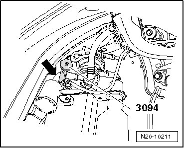
- Set the valve - D - to "Test".
- Observe the pressure gauge - C - and flow meter - E -. The fuel system is filled if the flow quantity decreases and the pressure increases to 10 in. H2O (25 mbar).
- After the pressure has stabilized, set the valve - D - to "Hold".
• After 5 minutes the pressure must not drop below 8 in. H2O (20 mbar).
- If the pressure no longer decreases, replace the leak detection pump.
If the pressure is not maintained for a minimum of 5 minutes or if no pressure is built up, localize the leak as follows:
- Fill the fuel system with smoke by setting the valve - D - to "Test".
- While the fuel system is being filled, press the smoke generator button - I - for approximately one minute.
The fuel system is now under pressure and filled with smoke.
- Check all the fuel system lines and hoses for escaping smoke. Also check the fuel tank sealing cap.
• Illuminate components and hoses with a strong flood light, the smoke will be more visible.
• To check for leaks at accessible locations, also use a ultrasonic measuring device or commercially available leak detection spray.
• Depending on how long the fault finding lasts, the smoke generator button may need to be pressed again. This ensures there is enough smoke present in the fuel system.
• To check the fuel pump and fuel filter flange, the assembly openings in the vehicle interior must be opened.
- Replace leaking hoses or components.
After completing the work, perform the "Check tank ventilation system for leaks" guided function using the vehicle diagnostic tester.
EVAP System Function Overview
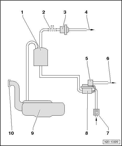
1 Evaporative Emission (EVAP) Canister
2 Adapter for Evaporative Emission Tester (KLI 9210/55-1) Installed Location
• Used with the fuel system leak test.
3 EVAP Canister Purge Regulator Valve 1 (N80)
4 Vent Line
• to the throttle valve control module (J338).
5 Solenoid Valve
• For the leak detection pump.
6 Vacuum Line
• To the intake manifold.
7 Air Filter Housing
• For the leak detection pump.
8 Leak Detection Pump (V144)
9 Fuel Tank
10 Cap
Leak Detection Pump, Checking Vacuum Supply
Special tools, testers and auxiliary items required
• Turbocharger Tester (V.A.G 1397A)
• T-piece (251 201 346)
• 6 mm Hose
• Leak detection pump (V144) installed location: In the right rear wheel housing under the wheel housing liner.
- Remove right rear wheel and wheel housing liner.
- Disconnect the vacuum line - 1 - from the leak detection pump.
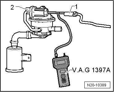
- Connect the turbocharger tester (V.A.G 1397A) with the T-piece and 6 mm hose between the vacuum line - 1 - and the leak detection pump - 2 -.
- Turn on measuring range I (absolute pressure measurement).
- Connect the vehicle diagnostic tester and start the engine.
- Select Guided Functions on the vehicle diagnostic tester.
- Select "Check tank ventilation system for leaks" guided function.
- Activate the test.
- While the test is running, observe the display on the turbocharger tester (V.A.G 1397A).
• The pressure must pulsate and must not rise above 0.700 bar (absolute pressure) during the test.
- If the pressure rises above 0.700 bar during the test, the vacuum supply is too low. Check the vacuum line to the intake manifold for kinks or blockages.