Intake Manifold
Intake Manifold Overview
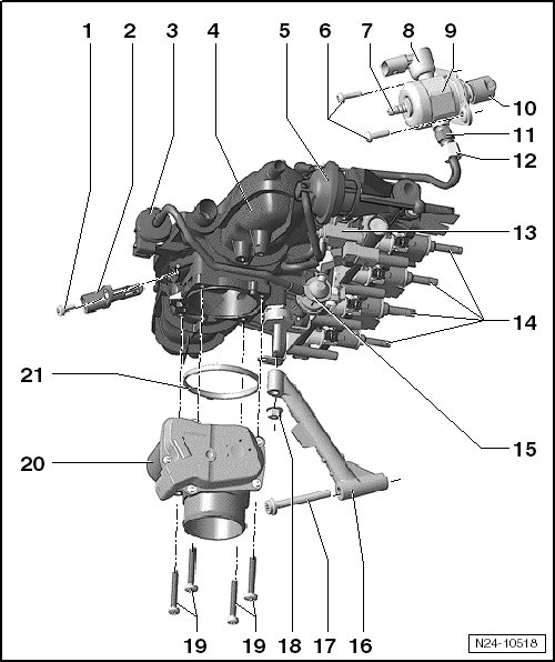
1 Bolt
• 5 Nm
2 Intake Air Temperature Sensor (G42)
3 EVAP Canister Purge Regulator Valve 1 (N80)
• With the double check-valve, a single component.
4 Intake Manifold
5 Vacuum Diaphragm for the Channel Separating Plate
6 Bolts
• M6 threads = 8 Nm + 90° (1/4) additional turn.
• M8 thread = 20 Nm.
• Always replace.
7 Connection for the Fuel Line from the Fuel Tank
8 Fuel Pressure Regulator Valve (N276)
9 High Pressure Pump
• With the fuel pressure regulator valve.
10 Roller Tappet
• Remains inserted in the cylinder head after removing the high pressure pump, removable.
11 Connection, High Pressure Fuel Line
• 22 Nm
12 Fuel Line to the Fuel Rail
• 18 Nm
13 Intake Manifold Runner Control Valve (N316)
14 Fuel Injector
15 Double Check-Valve
• With the EVAP canister purge regulator valve 1 as one unit.
16 Intake Manifold Support
17 Bolt
• 23 Nm
18 Nut
• 10 Nm
19 Bolts
• 5 Nm
• Quantity: 4
20 Throttle Valve Control Module (J338) , Electronic Power Control (EPC) Throttle Drive (G186)
• EPC throttle drive angle sensor 1 (G187) and EPC throttle drive angle sensor 2 (G188).
21 Seal