EVAP System Component Overviews
EVAP System Component Overviews
=> [ EVAP System Overview ]
Eos => [ EVAP System Components ]
• Hose connections are secured with either spring-type or clamp-type clips.
• Hose clip pliers (VAS 6340) or hose clip pliers (VAS 6362) are recommended for installing space saving clamps.
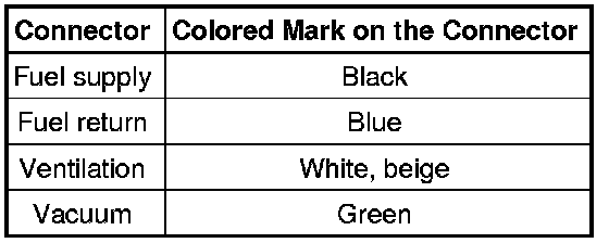
The connectors for fuel, vacuum and ventilation lines are marked with colors. There is either a colored dot on the connector or the release button is the corresponding color.
EVAP System Overview
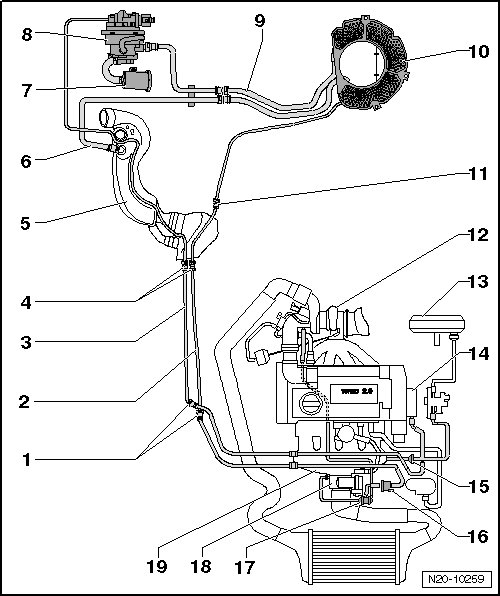
1 Separating Point
• On the right, front side in the engine compartment under the coolant expansion tank.
2 Vent Line
• White
• From the Evaporative Emission (EVAP) canister to the EVAP canister purge regulator valve 1.
• Installed position: On the right on the underbody.
• Secured to the fuel tank.
3 Vent Line
• Green
• From the engine to the leak detection pump.
• Installed position: On the right on the underbody.
• Secured to the fuel tank.
4 Separating Point
• On the right, front of the fuel tank in the area of the fuel filter.
5 Fuel Filler Tube
6 Vent Line
• From the filler connection to the EVAP canister.
7 Air Filter Housing
• For the leak detection pump.
8 Leak Detection Pump (V144)
• Component location: Inside the right rear wheel housing.
• Removing and installing, refer to one of the following:
• GTI, refer to => [ Leak Detection Pump (V144) ] Leak Detection Pump (V144).
• Eos, refer to => [ Leak Detection Pump (V144) ] Leak Detection Pump (V144).
• Checking the fuel system for leaks, refer to => [ Fuel System, Checking for Leaks ] Fuel System, Checking for Leaks.
9 Connecting Line
• From the leak detection pump to the EVAP canister.
• Clipped onto the bracket.
10 EVAP Canister
• Component location: Bottom of the spare tire wheel well.
• Removing and installing, refer to => [ EVAP Canister ] EVAP Canister.
11 Separating Point
• On the right rear of the fuel tank.
12 Turbocharger
13 Brake Booster
14 Vacuum Pump
15 Non-Return Valve
• Installed position: Arrow points in the direction of flow.
16 EVAP Canister Purge Regulator Valve 1 (N80)
• Checking, refer to the vehicle diagnostic tester.
17 Double Check-Valve
• Checking, refer to => [ Double Check-Valve, Checking ] Testing and Inspection.
18 Throttle Valve Control Module (J338)
• Removing and installing, refer to => [ Throttle Valve Control Module (J338) ] Removal and Replacement.
19 Intake Manifold
EVAP System Components, Eos
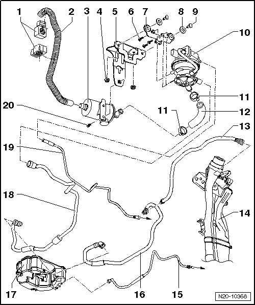
1 Hose Bracket
2 Ventilation Line
• To remove and install, remove the bumper.
3 Air Filter Housing
• For the leak detection pump.
4 Nut
• 6 Nm
5 Bracket
• For the leak detection pump.
6 Bolt
• 3 Nm
7 Mounting Plate
8 Rubber Bushing
9 Bolt
• 8 Nm
10 Leak Detection Pump (V144)
• Component location: Inside the right rear wheel housing.
• Removing and installing, refer to => [ Leak Detection Pump (V144) ] Leak Detection Pump (V144).
• Checking the fuel system for leaks, refer to => [ Fuel System, Checking for Leaks ] Fuel System, Checking for Leaks.
11 Hose Clamp
12 Connecting Hose
13 Vent Line
• Behind the wheel housing liner.
14 Fuel Tank
15 Vent Line
• To the EVAP canister purge regulator valve 1 (N80).
• To remove, press the release button.
16 Vent Line
• On the underbody.
17 Evaporative Emission (EVAP) Canister
• Component location: Bottom of the spare tire wheel well.
• Removing and installing, refer to => [ EVAP Canister ] EVAP Canister.
18 Connecting Line
• EVAP canister/leak detection pump.
19 Vacuum Line
• To the intake manifold.
20 Bolt
• 2 Nm