View 1
EVAP System Schematic Overview
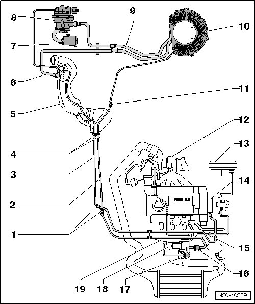
1 Separating Point
• In the front of the engine compartment on the right side, under the coolant expansion tank.
2 Vent Line
• White
• From the Evaporative Emission (EVAP) canister to the EVAP canister purge regulator valve 1.
• Installed position: On the right side of the underbody.
• Attached to the fuel tank.
3 Vent Line
• Green
• From the engine to the leak detection pump.
• Installed position: On the right side of the underbody.
• Attached to the fuel tank.
4 Separating Point
• In front of the fuel tank on the right side, near the fuel filter.
5 Filler Tube
6 Vent Line
• From the filler tube to the EVAP canister.
7 Air Filter
• For the leak detection pump.
8 Leak Detection Pump (V144)
• Installed location: Under the liner in the right rear wheel housing.
• Removing and installing, refer to => [ Leak Detection Pump ] Service and Repair.
• Fuel system, checking for leaks. Refer to => [ Fuel System, Checking for Leaks ] Fuel System, Checking For Leaks.
9 Connecting Line
• From the leak detection pump to the EVAP canister.
• Attached to the bracket.
10 EVAP Canister
• Installed location: On the bottom of the spare tire wheel well.
• Removing and installing, refer to => [ EVAP Canister ] Service and Repair.
11 Separating Point
• On the back of the fuel tank, on the right side.
12 Turbocharger
13 Brake Booster
14 Vacuum Pump
15 Non-Return Valve
• Installed position: Arrow points in the direction of flow.
16 EVAP Canister Purge Regulator Valve 1 (N80)
• Checking, refer to the vehicle diagnostic tester.
17 Double Check-Valve
18 Throttle Valve Control Module (J338)
19 Intake Manifold