Front Fender Overview
Front Fender Overview
• Removing and installing the left fender is described here. Removing and installing the right fender is identical.
• The illustration shows a left fender. The right fender is identical.
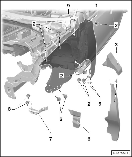
1 Fender
2 Bolt
• Tightening specification: 6 Nm
• A-pillar, quantity: 1
• Sill panel, quantity: 2
• Wheel housing, quantity: 2
• Fender brace, quantity: 2
• Fender connecting piece, quantity: 2
3 Foam Piece
• Inserted between the fender and the upper front longitudinal member, refer to => [ Fender Insulation Component Locations ] Locations.
4 Fillet Plate Insulation
• Installed in front of the fillet plate on the fender, refer to => [ Fender Insulation Component Locations ] Locations.
5 Spacer
• Spacer (AKL 381 035 50)
6 Filler Piece
• Glued to the A-pillar with butyl rubber.
• The filler piece remains attached to the A-pillar when removing the fender. Refer to => [ Fender Insulation Component Locations ] Locations.
7 Fender Brace
• Removing and installing, refer to => [ Fender Brace ] Fender Brace.
8 Bolt
• Tightening specification: 6 Nm
• Quantity: 2
9 Nut
• Tightening specification: 6 Nm
• Quantity: 1, at fender connecting piece.