Subframe Bonded Rubber Bushing, FWD
Subframe Bonded Rubber Bushing, FWD
Special tools, testers and auxiliary items required
• Installation device (3372)
• Assembly tool (T10214)
• Assembly tool (T10244)
• Thrust plate (VW 401)
• Thrust plate (VW 402)
Pressing Out the Bonded Rubber Bushing
- Remove subframe. Refer to => [ Subframe without Steering Gear ] Subframe Without Steering Gear.
- Attach (T10244) to subframe.
- Press out both bonded rubber bushings at the same time as depicted in the illustration.

• The flattened side of the installation device (3372/1) must face toward (T10244) insert - A -, otherwise insert can be damaged.
• Tube (T10244/3) has a larger and a smaller inner diameter. Subframe must contact larger inner diameter of (T10244/3).
Pressing In the Bonded Rubber Bushing
- Bolt both bonded rubber bushings with original bolt, cutouts - arrows - must align when doing this.
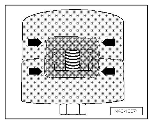
- Insert the bolted bonded-rubber bushing with bolt head facing downward into tube (T10214/2).
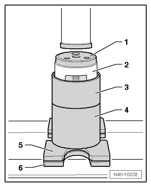
1. Thrust piece (T10214/3)
2. Bonded rubber mount
3. Tube (T10214/2)
4. Tube (T10214/1)
5. (VW 401)
6. (VW 402)
- Press bonded rubber bushing - 1 - in until dimension - a - has been obtained.
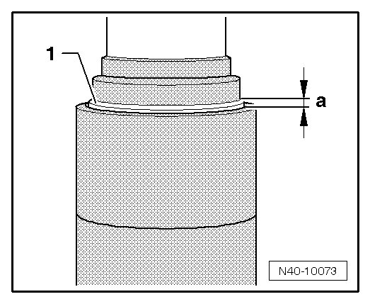
Dimension - a - = 2 - 3 mm.
• There are two different versions of the pendulum support bonded rubber bushing: the T version - I - and the V version - II -.
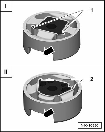
• For the correct allocation, refer to the Electronic Parts Catalog (ETKA).
I The corners on the inner core - 1 - face toward the opening for the pendulum support - arrow - (T version).
II The corners on the inner core - 2 - face away from the opening for the pendulum support - arrow - (V version).
T Version of the Bonded Rubber Bushing
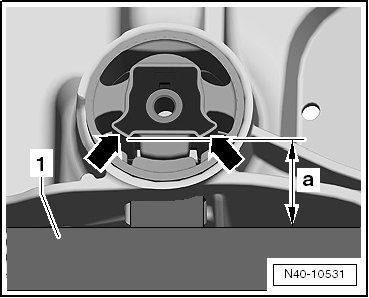
- Align (T10214/2) on subframe with pressed in bonded rubber bushings.
• The corners on the inner core of the bonded rubber bushing - arrows - must face toward the (T10244) - 1 -.
• The corners on the inner core of the bonded rubber bushing - arrows - must lie parallel with the edge of the (T10244) - 1 -.
Distance - a - must be identical at left and right to guarantee parallelism.
V Version of the Bonded Rubber Bushing
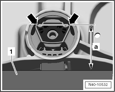
- Align (T10214/2) on subframe with pressed in bonded rubber bushings.
• The corners on the inner core of the bonded rubber bushing - arrows - must face away from the (T10244) - 1 -.
• The corners on the inner core of the bonded rubber bushing - arrows - must lie parallel with the edge of the (T10244) - 1 -.
Distance - a - must be identical at left and right to guarantee parallelism.
Procedure for Both Versions
- Place subframe on smaller interior diameter of (T10244/3).
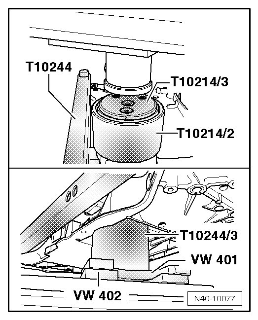
- Press in bearing on stop and until a pressing force of 20 kN has been obtained.
- Remove (T10244) from subframe and check seating of the pressed in bonded rubber bushing.
• The outer diameter - 1 - of both bonded rubber bushings must not project more than 2 mm into the area of the pendulum support opening.
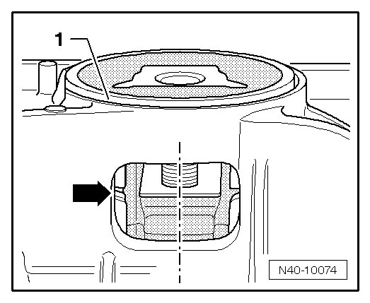
• Cutouts of bonded rubber bushings must lie at center in opening of subframe.
• A gap - arrow - between bonded rubber bushings is permitted.
- Install subframe. Refer to => [ Installing ] Subframe Without Steering Gear.