Steering Column Switch Base Carrier, Valeo
Steering Column Switch Base Carrier, Valeo
Special tools, testers and auxiliary items required
• Angled hand drill
• Torque Wrench (V.A.G 1410)
The removal and installation of individual steering column switch components must be done in a specified sequence. Refer to => [ Steering Column Switch Components, Removal and Installation Sequence ] Steering Column Switch Components, Removal and Installation Sequence.
• The shear bolts - 1 - on the electronic steering column lock control module (J764) must be drilled out in order to remove the steering column switch base carrier - 2 -. New shear bolts will be needed for installation later. Refer to Electronic Parts Catalog (ETKA).

• Before drilling out shear bolts, always make sure all components secured to steering column switch base carrier are removed beforehand.
• By drilling out, drill shavings can reach the neighboring components, which can lead to damage and malfunctions!
• When removing the steering column switch components, observe the specified sequence. Refer to => [ Steering Column Switch Components, Removal and Installation Sequence ] Steering Column Switch Components, Removal and Installation Sequence.
Always follow the instructions in the Repair Information exactly when disconnecting and connecting the battery. Refer to battery in engine compartment => [ Battery, Disconnecting and Connecting ] Service and Repair or battery in luggage compartment => [ Battery, Disconnecting and Connecting ] Service and Repair.
Removing
- Disconnect the battery. Refer to battery in engine compartment => [ Battery, Disconnecting and Connecting ] Service and Repair or battery in luggage compartment => [ Battery, Disconnecting and Connecting ] Service and Repair.
- Remove all the components attached to the steering column switch base carrier in the sequence given. Refer to => [ Steering Column Switch Components, Removal and Installation Sequence ] Steering Column Switch Components, Removal and Installation Sequence.
The steering column switch base carrier can be removed one all the components attached to it are removed.
- Drill out the shear bolts - 1 - on the electronic steering column lock control module (J764) - 3 -.
• Bolts M8 - 1 -, core hole diameter 6.8 mm.
- Disconnect the connector on the back of the electronic steering column lock control module - 3 - and then remove the control module together with the steering column switch base carrier - 2 - from the steering column.
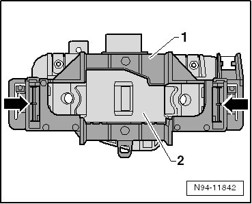
- Open the tabs - arrows - on the steering column switch base carrier and remove the steering column switch base carrier - 1 - from the electronic steering column lock control module - 2 -.
Installing
- Install the steering column switch base carrier - 1 - on the electronic steering column lock control module - 2 -.
- Slide the steering column combination switch (E595) onto the steering column switch base carrier until it latches.
- Slide the pre-assembled unit from the electronic steering column lock control module (J764) , the steering column switch base carrier and the steering column combination switch all the way onto the steering column and line them up with the threaded holes.
- Secure the electronic steering column lock control module - 1 - to the steering column with new shear bolts.

- Tighten the shear bolts - 1 - until the bolt heads shear off.
Further installation is in the reverse sequence to removal.
• Code the new electronic steering column lock control module after installing. Refer to => [ Electronic Steering Column Lock Control Module (J764), Coding ] Electronic Steering Column Lock Control Module (J764), Coding.