Subframe Overview
Subframe Overview
• Welding and straightening work on supporting or wheel carrying components of the suspension is not permitted.
• Always replace self-locking nuts.
• Always replace corroded bolts/nuts.
• Bonded rubber bushings can only be turned to a limited extent. Therefore, the threaded connections of the components with bonded rubber bushings should only be tightened when the wheel bearing housing is lifted (curb weight position).
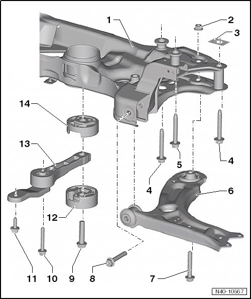
1 Subframe
• Locating, refer to => [ Subframe Securing ] Subframe Securing
• Removing and installing without steering gear, refer to => [ Subframe without Steering Gear ] Service and Repair
• Removing and installing with hydraulic steering gear refer to => [ Subframe and Steering Gear, Hydraulic Steering Gear ] Subframe and Steering Gear, Hydraulic Steering Gear
• Removing and installing with electro-mechanical steering gear, refer to => [ Subframe and Steering Gear, Electro-Mechanical Steering Gear ] Subframe and Steering Gear, Electro-Mechanical Steering Gear
• Servicing, refer to => [ Subframe ] Overhaul
• Allocation, refer to the Parts Catalog
2 Nut
3 Backing plate
• Always replace if removed.
• Installed position => [ Intermediate plate installed position ]
4 Bolt
• 70 Nm + 180°
• M12 x 1.5 x 100
• Always replace if removed.
5 Bolt
• 70 Nm + 180°
• M12 x 1.5 x 90
• Always replace if removed.
6 Control Arm
• Replace with ball joint if damaged.
• Removing and installing, refer to => [ Lower Control Arm ] Lower Control Arm
• Removing and installing (left side of the vehicle with a DSG transmission or automatic transmission) refer to => [ Control Arm, Left Side of Vehicle with DSG or Automatic Transmission ] Control Arm, Left Side of Vehicle with DSG or Automatic Transmission
7 Bolt
• 70 Nm + 180°
• M12 x 1.5 x 80
• Always replace if removed.
8 Bolt
• 70 Nm + 180°
• M12 x 1.5 x 80
• Always replace if removed.
9 Bolt
• 100 Nm + 90°
• M14 x 1.5 x 70
• Tighten only when the pendulum support is bolted to the transmission
• Always replace if removed.
10 Bolt
• 50 Nm + 90°
• M10 x 75
• Always replace if removed.
11 Bolt
• 50 Nm + 90°
• M10 x 35
• Always replace if removed.
12 Lower Bonded Rubber Bushing for Pendulum Support
• Removing and Installing, refer to => [ Subframe ] Overhaul
13 Pendulum Support
• Bolt first to transmission, then to subframe
• There are different versions.
• Allocation, refer to the Parts Catalog
14 Upper Bonded Rubber Bushing for Pendulum Support
• Removing and Installing, refer to => [ Subframe ] Overhaul
Intermediate plate installed position
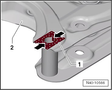
Insert the long side of the intermediate plate - 1 - so that it is perpendicular to direction of travel. The tabs - arrows - fit into the subframe - 2 -.