JD. Engine Falters or Stops With A/C On
JD. THE ENGINE FALTERS OR STOPS RUNNING WHEN THE AIR CONDITIONING (A/C) IS USED
JD1
Adjusting The Throttle Body (TB)
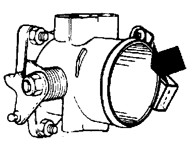
-Adjusting the TB JD1.
-Continue with DTM 2 JD2.
JD2
DIAGNOSTIC TEST MODE (DTM) 2
-Start the engine.
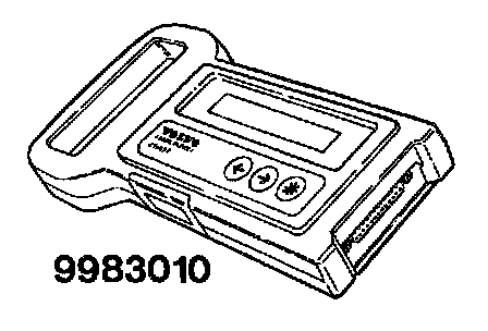
Go into DTM 2 in accordance with C. Fault tracing via the DLC.
-Continue with Checking the A/C control JD3.
JD3
Checking The Air Conditioning (A/C) Control
-Disconnect the pressure regulator (pressostat) connector located on the accumulator.
-Switch on the fan.
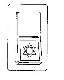
-Put the A/C control into the on position
The OBD system should respond with the code 1-1-4.
If the response code 1-1-4 Is obtained
-Check the pressure regulator JD7.
If there Is no response code
The control module is not receiving a signal from the A/C control when this is put in the on position.
-Connecting the test box JD4.
JD4
Connecting The Test Box
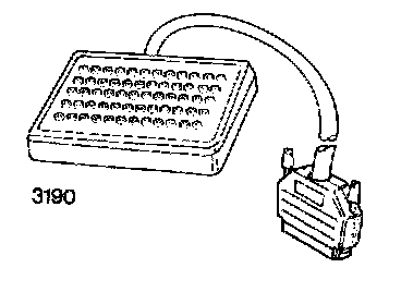
Connect the test box to MFI LH 2.4/LH 3.1 and check the connections to ground.
-Continue with Checking the A/C control and wiring JD5.
JD5
Checking The Air Conditioning (A/C) Control And Wiring
-Ignition off.
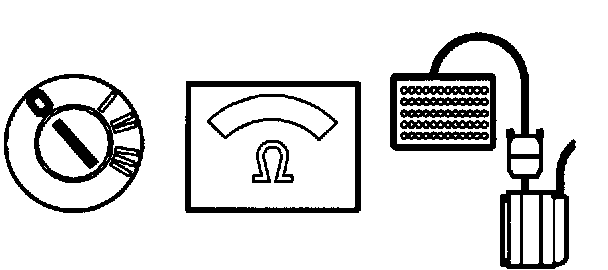
Connect an ohmmeter between #15 and #5 (GND). The ohmmeter should read approx. 35 OHMS when the A/C control is on and infinite resistance when the A/C control is off.
If this value is OK
-Check the signal from the NC control JD6.
If the reading is incorrect
-Check the wiring for breaks and contact resistance.
JD6
Checking The Signal From The Air Conditioning (A/C) Control
-Connect the control module to the test box.
-Put back the fuse you took out.
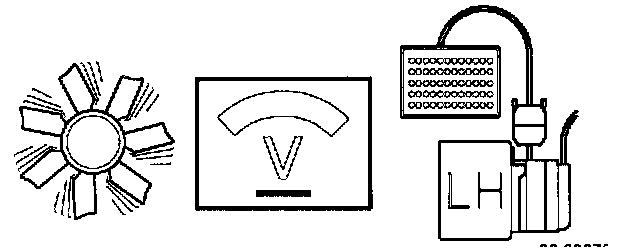
-Start the engine.
-Switch on the fan.
Connect a voltmeter between #15 and #5 (GND).
The voltmeter should read battery voltage when the A/C control is on and approx. 0 V. when the A/C control is off.
If this value is OK
Intermittent fault.
-Check the connections for loose contacts.
If the reading is incorrect
-Check the wiring for breaks and contact resistance.
JD7
Checking The Pressure Regulator
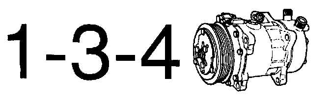
-Reconnect the pressure regulator (pressostat). The OBD system should respond with the code 1-3-4 when the compressor engages or disengages.
If the response code 1-3-4 is obtained
-Adjust in accordance with WA. Checking TB adjustment.
If there Is no response code
The control module is not receiving a signal from the pressure regulator when it engages the compressor.
-Connect the test box JD8.
JD8
Connecting The Test Box
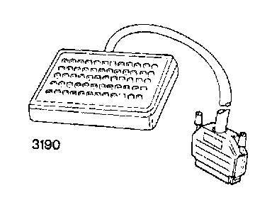
Connect the test box to MFI LH 2.4 or LH 3.1 and check the connections to GND in accordance with P1-P2.
-Continue with Checking the wiring to the A/C compressor JD9.
JD9
Checking The Wiring To The Air Conditioning (A/C) Compressor
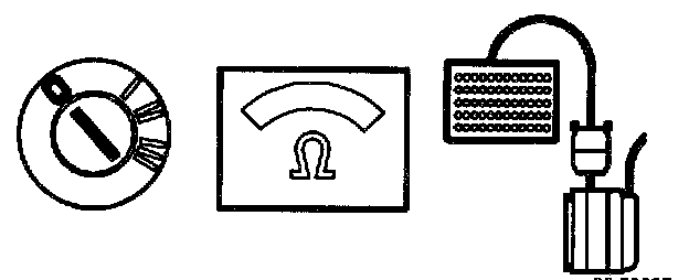
-Ignition off.
Connect an ohmmeter between #14 and #5 GND.
The ohmmeter should read approx. 3 OHMS.
If this value is OK
-Check the signal from the A/C compressor JD1.
If the reading is incorrect
-Check the wiring for breaks and contact resistance.
JD1O
Checking The Signal From The Air Conditioning (A/C) Compressor
-Connect the control module to the test box.
-Re-install system fuse.
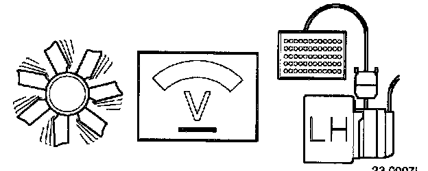
-Start the engine
-Switch on the fan and switch on A/C.
Connect a voltmeter between #14 and #5 (GND).
The voltmeter should read battery voltage when the A/C compressor is on and approx. 0 V. when the A/C compressor is off.
If this value is OK
-Repeat DTM 2 J02.
If the reading Is incorrect
-Check the wiring for breaks and contact resistance.