A/T Gear Lever - Repair/Replacement
SECTION4
GROUP
43
NO.
917
DATE:
April 1994
RE:
Repair/replacement of gear lever unit on automatics
940/960 1993->
Fault tracing
Repairs
Maintenance
REFERENCE:
TP 31642/1; AUTO TRANSMISSIONS TP 31706/2; AUTOMATIC TRANSMISSION
Repair/replacement of gear lever unit on automatics
A1
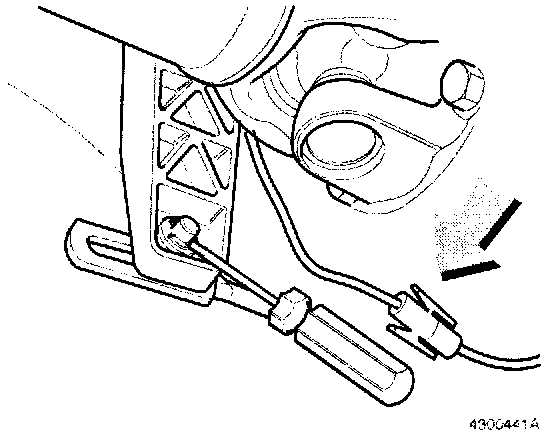
Removal of gear lever unit, AW
- Turn ignition off.
- Disconnect battery ground lead.
- Raise car on lift.
- Disconnect gear lever arm from control rod.
- Open connector between gear lever unit and gearbox
- Lower car.
A2
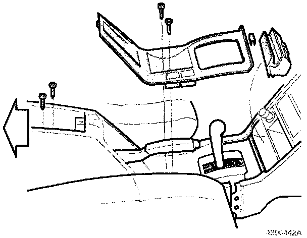
Removal of panels
- Remove ashtray and holder.
- Remove center console panel screws (two) under handbrake lever.
- Remove clip at front of panel.
- Remove panel.
- Remove tunnel cover retaining screws in storage compartment.
- Pull cover backward.
A3
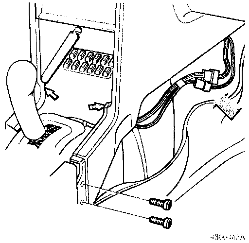
- Slacken but do not remove screws in side panel support bracket.
- Release bracket at right-hand side and swing upward towards left.
- Remove screws at rear edge of right-hand side panel.
- Fold aside carpet under right-hand side panel to expose connectors.
- Undo connectors.
- Pull wiring forward under air duct.
A4
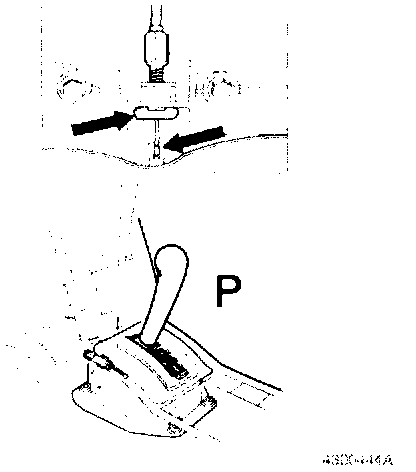
Removal of key lock cable
- Check that gear selector lever is in position P.
- Remove cable adjuster circlip at gear lever end.
- Lift rubber edge of gear lever unit panel and unhook cable from gear lever arm.
A5

Removal of gear lever unit
- Remove screws (four) from gear lever unit.
- Remove unit.
Transfer of components
A6
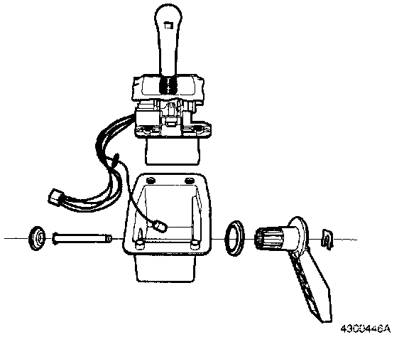
Dismantling of gear lever unit
- Remove spring clip.
- Remove rubber plug.
- Remove gear lever arm.
- Tap out spindle.
- Remove unit from housing.
- Remove rubber grommet and wiring from housing (AW)
A7
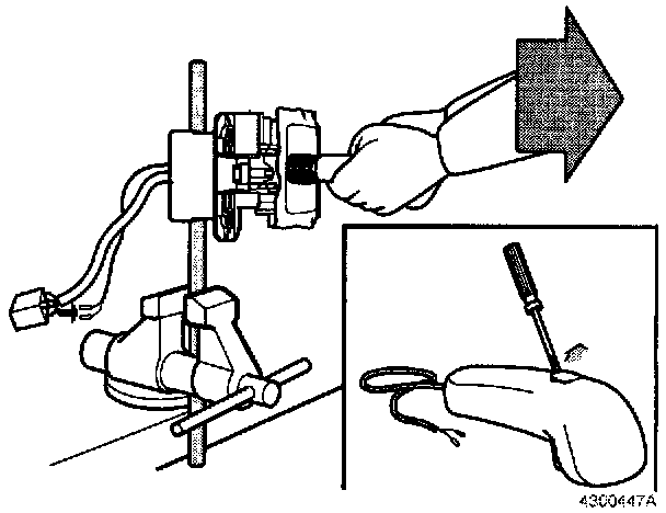
Removal of gear lever knob, AW
- Free lead from overdrive switch from other wiring and remove terminal pins from connector.
- Ensure that lead can pass freely through unit.
- Insert 3/8" rod in spindle hole. Clamp bar in vice and pull off knob.
Note!
Considerable force is required.
- Remove overdrive switch button from knob. Use small screwdriver.
- Withdraw lead through knob.
- Inspect lead and terminals. Replace lead if damaged.
- Discard old knob (do not reuse old knob).
A8
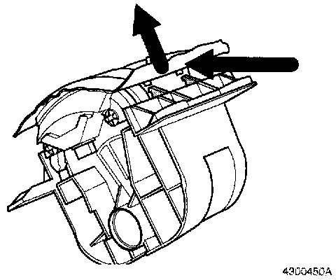
Removal of gear indicator panel
- Press in rear edge of panel to release snap catch.
- Remove panel.
A9
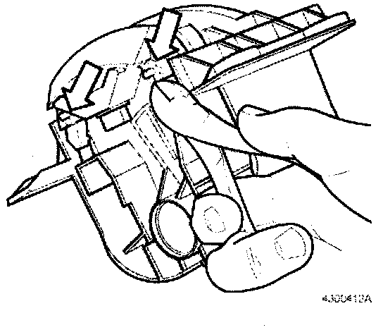
Transfer of light strip with indicator and start inhibitor switch
- Cut off locking clips.
A10
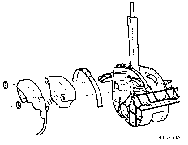
- Transfer start inhibitor switch, ensuring that slot in switch engages projection on gear lever.
- Transfer indicator and light strip.
- Install new locking clips.
A11
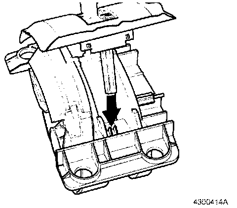
Installation of indicator panel
- Position shift lock override button in panel and gear lever unit.
A12
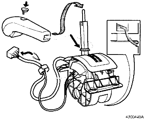
Installation of gear selector knob, AW Install new knob.
- Push cable into new knob.
- Install overdrive switch.
- Pass cable through gear lever unit.
- Secure cable in strain reliever slot in underside of unit.
- Ensure that cable runs behind locking tab in unit.
- Secure cable to other wiring with cable tie.
- Reinstall connector terminal pins.
- Ensure that plastic collar is in place and correctly positioned on knob.
- Press knob onto lever.
Note!
Considerable force is required.
A13
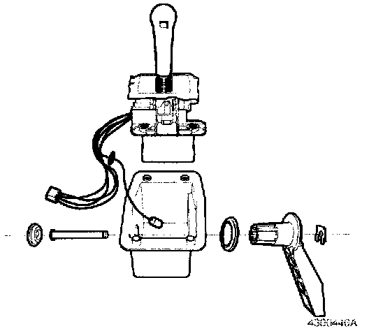
Reassembly of gear lever unit
Install:
- Wiring and rubber grommet in housing (AW)
- Gear lever unit in housing
- Rubber ring on spindle, with tapered side facing inward
- Gear lever arm (can be installed in one position only)
- Spindle
- Spring clip
- Rubber plug
A14
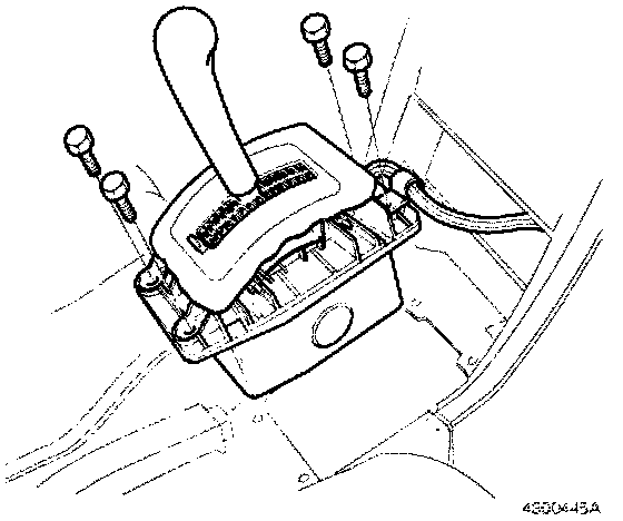
Installation of gear lever unit
- Install gear lever unit.
- Attach cable clip to right front screw.
- Tighten screws to 8 N-m (6 ft.lb.).
- Position wiring between side panels.
- Raise air duct using large screwdriver and push in wiring under duct.
A15
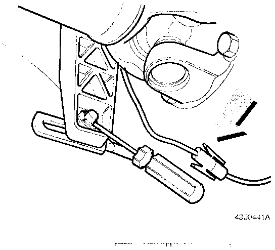
Reconnection of control rod
- Raise car on lift.
- Reconnect connector between gear lever unit and gearbox.
- Reconnect control rod to gear lever arm with washer and circlip.
- Lower car.
- Reconnect battery ground lead.
A16
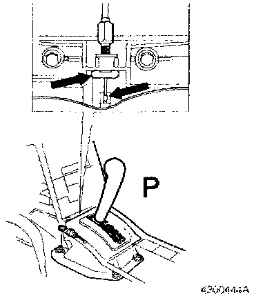
Installation of key lock cable (cars with key lock function)
- Check that gear lever is in position P.
- Connect cable at gear lever end.
- Install circlip.
A17
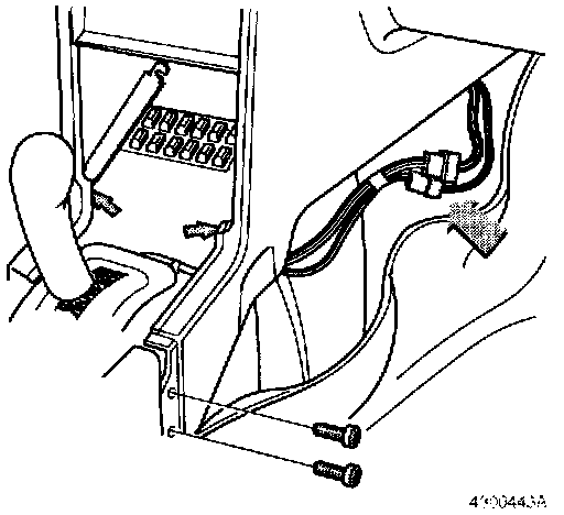
Installation of right-hand side panel
- Reconnect connectors.
- Check key lock function as described in Service Bulletin 4-43-708 (940) procedure A22-A24, or Service Bulletin 4-43-709 (960) procedure A16-A18.
- Refit carpet under right-hand side panel.
- Tighten both screws at rear edge of panel.
- Lower support bracket into position between side panels and hook in position on right-hand side.
- Tighten screws.
Test operation A18
Adjust clearance between control rod and gear lever arm as described in SB 4-43-911.
Check shift lock override.
Check overdrive switch.
A19
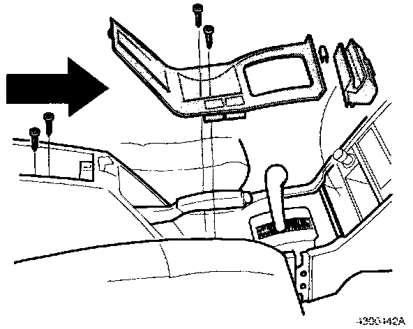
Installation of tunnel cover panel and center console
- Move tunnel cover panel forward.
- Tighten both screws in storage compartment.
- Place center console in position.
- Attach clip at front edge of console.
- Tighten screws under handbrake lever.
- Install ashtray and holder.
- Connect battery ground lead.
- Reset radio codes.
WARRANTY STATEMENT:
Claims may be submitted under the New Car Limited Warranty when a manufacturing defect is present using claim type: 01
Operation No. Labor description Time allowance
432523 Gear lever unit, repair/replace 0.8 hr