Specifications, Final Drive
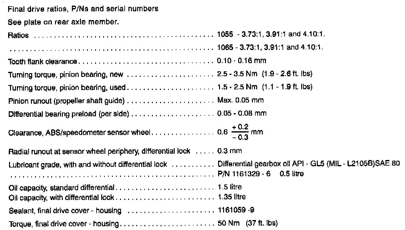
Specifications, final drive
Note!
Before disconnecting propeller from drive flange: Carefully mark position of shaft relative to drive flange. Also check if balancing bolts are installed. Where applicable, note positions and lengths of bolts.

Note!
Proceed as follows if the propeller shaft is reinstalled without replacing the rear joint, or without dismantling or replacing the drive flange on the final drive:
Install shaft in accordance with marking applied when dismantling (see box above), using new bolts of the same length as those removed.
Proceed as follows if the propeller shaft has been replaced, or if the drive flange on the final drive has been removed or replaced:
Install shaft in accordance with marking applied when checking radial runout of pinion guide. Position pink marking on shaft as close to marking on drive flange as permitted by hole spacing. Use new bolts of standard length only.
Note!
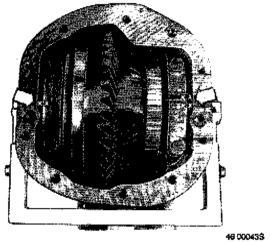
When dismantling drive, mark differential bearing caps and corresponding locations in housing.
Do not mark joint face.
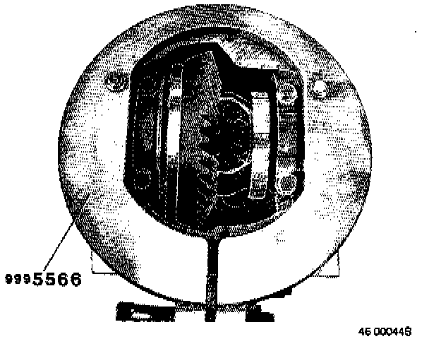
When removing/installing [1][2]differential Final drive housing may be expanded by a maximum of 0.35 mm.
Mount expander 999 5566 in position using two of cover bolts. Do not tighten.
First tighten expander screw lightly, then tighten through a maximum of 1 turn, corresponding to expansion of 0.25 - 0.35 mm.
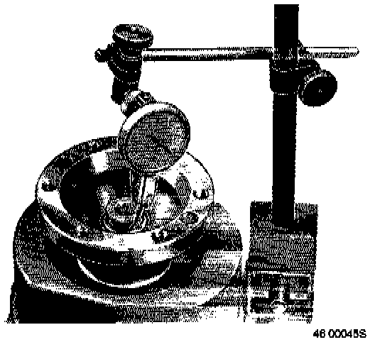
When checking radial runout of pinion
Note!
The following must be carried out in every instance when replacing the pinion seal/drive flange or when reconditioning the final drive.
Measure radial runout of pinion guide. Value should not exceed 0.05 mm. Always install new nut. Replace nut if maximum runout is exceeded since pinion runout is affected by nut tolerances.
Torque 180 - 200 N-m (133 - 147 ft.lbs).
Note!
200 N-m (147 ft.lbs) must not be exceeded.
^ Recheck radial runout.
Mark highest point (i.e. point at which runout is maximum) on periphery of drive flange. Use felt pen. Marking should be as close to pink marking on propeller shaft as permitted by hole spacing in universal joint and flange.