Flywheel - Revised Replacement Part
SECTION2
GROUP
28
NO.
820
DATE
Oct. -96
New replacement part flywheel
850 M/Y 1993-95
REFERENCE: TP 2101201 SECTION 2(20-22,25-26) ENGINES B5204, B5234, B5252, B5254; 850 1992-
TP 2102201, SECTION 2(21) RECONDITIONING ENGINES B5202, B5204, B5234, B5252, B5254; 850 1992-
TP 32127/2, SECTION 3 (39) WIRING DIAGRAMS; 850 1993
TP 3903202, SECTION 3(39) WIRING DIAGRAMS; 850 1994
TP 3907202, SECTION 3 (39) WIRING DIAGRAMS; 850 1995
TP 3911202, SECTION 3 (39) WIRING DIAGRAMS; 850 1996
New replacement part flywheel
For up to and including model year '95 850, only the following flywheels are available as replacement parts. The flywheels were introduced in model year '96.
P/N new type of flywheel: 9146880-1 Non turbo
1271572-8 Turbo
Special tools: 9814235-9 Terminal repair kit
When replacing the older version with the new flywheel the position of the engine speed (RPM) sensor wires must be reversed in the connector at the engine harness. If the wires are not reversed the vehicle will not start after the new flywheel is installed.
Note:
If the replaced flywheel is of the same type as the new one, there is no need for changing the position of the engine speed (RPM) sensor wires.
Please make the following notation in the above sections of the Service Manuals:
"See Service Bulletin 2-28-820, when changing the flywheel on model year 1992 - 1995".
Older flywheels (A)
have holes drilled in them which provide the engine speed (RPM) sensor with signals.
The new version of the flywheel (B)
has milled grooves which provide the engine speed (RPM) sensor with signals.
The method of replacing the flywheel is contained in:
- Service Manual Section 2(20-22, 25-26) Engines B5204, B5234, B5252, B5254 850 1992-
TP 2101201 section A0
- Service Manual Section 2(21) Reconditioning Engines B 5202, B5204, B5234, B5252, B5254 850 1992- TP 2102201 section A2 Removal and section M8 Installation.
Reversing the position of the engine harness wires
The polarity must be reversed in the connector between the engine compartment cabling and the engine speed (RPM) sensor cabling.
- Separate connector halves.
- Remove the insulation tape between the protective sleeve and the connector on the engine compartment cabling. Note the position of the cables.
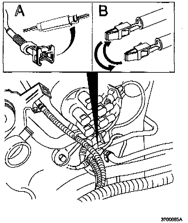
- Remove the two cables from the connector. Use terminal removal tool 981 4228-4(A), or 951 2631-4.
Reinstall the cables in the connector in the opposite terminals: (B).
- the cable from terminal 1 should be installed in terminal 2
- the cable from terminal 2 should be installed in terminal 1
- Check that the gasket in the connector is still there and is positioned correctly.
- Press grease, P/N 116 1417-9 into the female contacts.
- Wind insulation tape onto the cabling between connector and protective sleeve.
- Connect connector.
Start the engine. If the engine does not start
Check:
- that the reversed cables are properly installed into the connector on the engine compartment cabling.
- that the connectors between engine compartment cabling and the engine speed (RPM) sensor cabling are connected.
WARRANTY STATEMENT: Claims may be submitted under the New Car Limited Warranty when a manufacturing defect is present using claim type: 01
operation no. Labor description Time allowance
28901-3 Engine speed (RPM) sensor 0.1 hrs
reversing polarity