No Power Supply To Control Module
CHECKING GROUND POINTS TO CONTROL MODULE1. Ignition off.
2. Connect test box between control module and connector.
3. Connect an ohmmeter between ground (chassis) and # 4, 9, 10, 20, 21, 34 on test box. Ohmmeter reading should be approx. 0 in each case.
4. If all readings are correct: This means these points are at 0 volts (provided the battery negative terminal is connected to the chassis). Return to fault-tracing where you left off to connect the test box.
5. If any reading is incorrect: If the ohmmeter reading is infinite, there is an open-circuit to ground in a circuit. Check connection between ground lead and ground (chassis).
CHECKING POWER SUPPLY TO CONTROL MODULE
1. Ignition off.
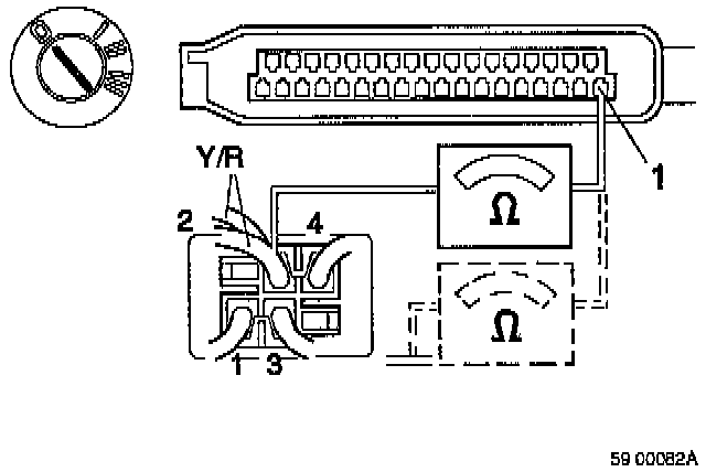
2. Connect a voltmeter between # 20 (0 volts) and # 1 on test box.
3. Ignition on. Voltmeter reading should equal battery voltage (approx. 12 volts).
4. If voltmeter reads 0 volts: Ignition off Check 10 AMP fuse on transient surge protection relay. Check lead between ABS connector pin 1 and transient surge protection relay pin 2 for short-circuit or open-circuit.
5. If fault persists: Check power supply to transient surge protection relay.
CHECKING 0 VOLTS ON TRANSIENT SURGE PROTECTION RELAY
1. Ignition off
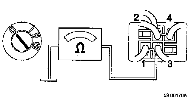
2. Connect an ohmmeter between ground point (0 volts) and transient surge protection relay pin 3. Ohmmeter reading should be 0 ohms.
3. If reading is incorrect: If ohmmeter reads infinite resistance, there is an open-circuit in the lead.
Note: Once fault has been put right, there should be battery voltage at control module pin 1. If there is no power at the control module, go to Checking power supply to transient surge protection relay.
CHECKING POWER SUPPLY TO TRANSIENT SURGE PROTECTION RELAY
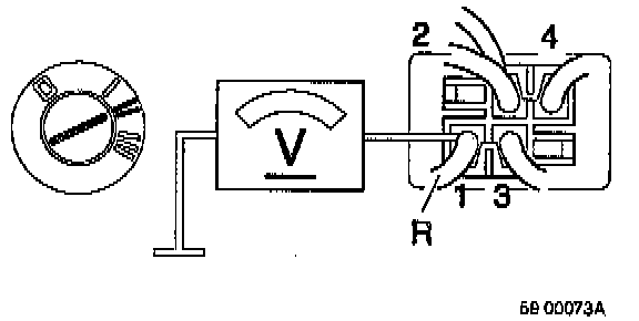
1. Connect a voltmeter between ground point (0 volts) and transient surge protection relay pin 1.
2. Ignition on.
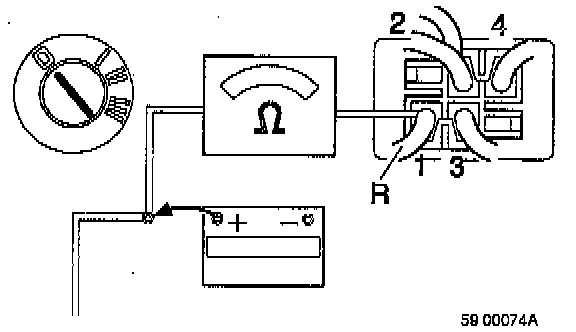
3. Voltmeter reading should equal battery voltage (approx. 12 volts).If reading is incorrect: Turn Ignition off. Undo lead to battery positive terminal. Connect an ohmmeter between transient surge protection relay pin 1 and lead disconnected from battery positive terminal. Ohmmeter reading should be approx. 0 ohms.
4. If reading is incorrect: If ohmmeter reads infinite resistance, there is an open-circuit in a lead somewhere. Deal with open-circuit.
5. Reconnect positive lead to battery.
NOTE: There should now be battery voltage at control module pin 1. If there is no power to the control module, go to Still no power to control module.
STILL NO POWER TO CONTROL MODULE
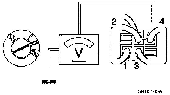
1. Connect a voltmeter between ground point (0 volts) and transient surge protection relay pin 4.
2. Ignition on.
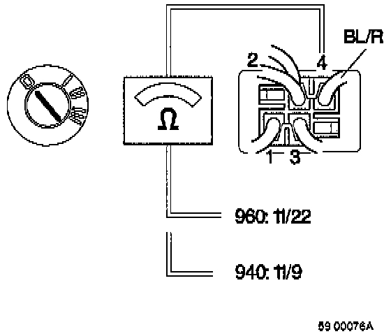
3. Voltmeter reading should equal battery voltage (approx. 12 volts). If reading is incorrect Check fuse 11/22 on fuse panel. If the fault persists: Turn Ignition off. Connect an ohmmeter between transient surge protection relay pin 4 and fuse 11/22 on fuse panel.
4. Ohmmeter should read approx. 0 ohms. Go to Checking lead resistance.
5. If reading is incorrect: If ohmmeter reads infinite resistance, there is an open-circuit in a lead somewhere.
CHECKING LEAD RESISTANCE
1. Ignition off.
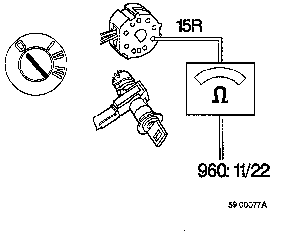
2. Connect an ohmmeter to ignition switch terminal 15R and fuse 11/22 on the fuse panel. Ohmmeter reading should be about 0 ohms if lead is OK.
3. If reading is incorrect: If ohmmeter reads infinite resistance, there is an open-circuit in a lead.
NOTE: After treatment, there should be battery voltage on ABS connector pin 1.
4. If there is still no power, replace transient surge protection relay.
5. Checking voltage. Turn Ignition off. Connect test box between control module and ABS connector. Connect a voltmeter across # 20 and # 1. Turn Ignition on.
6. Voltmeter reading should equal battery voltage (approx. 12 volts).
7. If voltmeter reading is 0 volts Check fuse on fuse panel 11/22
8. If fuse is intact Check lead resistance between ABS connector pin 1 and fuse as above.
CHECKING LEAD RESISTANCE
1. Ignition off.
2. Connect test box to ABS connector.
3. Connect an ohmmeter between # 1 and fuse. Ohmmeter should read about 0 ohms.
4. If reading is incorrect (infinite resistance): Open-circuit in lead.